
Related Manuals for REPLIGEN KrosFlo SYITF-2000


Summary of Contents for REPLIGEN KrosFlo SYITF-2000
- Page 1 KrosFlo® Systems User Guide For use with: · KrosFlo® KTF Tangential Flow Filtration (TFF) System · KrosFlo® KPS Perfusion (KPS) System · KrosFlo® TFDF® Tangential Flow Depth Filtration (TFDF) System IF.UG.IM_R1...
- Page 2 Customer shall refer to the terms and conditions of sale governing the transaction for any and all warranties for the Product. Repligen Corporation shall not be liable for errors contained herein or for incidental or consequential damages in connection with the furnishing, performance, or use of this material.
-
Page 3: Table Of Contents
User Guide User Guide KrosFlo® Systems Contents Introduction ......................... 7 Safety Precautions ........................ 7 2.1 Signal Words ........................... 7 2.2 Safety Symbol Icons ........................ 8 Safety Guidelines ........................9 3.1 Intended User Guide Audience ....................9 3.2 Intended Use of the System ....................10 3.3 Warnings for Moving, Installing, and Storing the System ............ - Page 4 User Guide User Guide KrosFlo® Systems 13. Performing System Maintenance ..................47 13.1 Making the System Safe for Maintenance ................47 13.2 Cleaning the System ......................47 13.3 Cleaning the Flow-path ......................47 13.4 Flow-path disassembly and storage ..................48 13.5 System Moving and Storage ....................
- Page 5 User Guide User Guide KrosFlo® Systems List of Tables Table 1. Signal words, definitions, and colors ..................7 Table 2. Safety Symbol Icons........................8 Table 3. KrosFlo® System Feature/Component Specifications ............. 15 Table 4. KrosFlo® System Electrical Specifications ................16 Table 5.
- Page 6 User Guide User Guide KrosFlo® Systems Abbreviations Ampere Celsius Concentration factor Centimeter Diafiltration volume Electrical schematic Europe Fahrenheit Functional design specification Feet General arrangement drawing Hardware design specification Human machine interface Kilograms TFDF Tangential depth filtration system lbs. Pounds Liquid-crystal display Liters per minute Meter Milliampere, or milliamp...
-
Page 7: Introduction
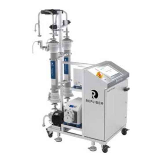
KrosFlo® Systems User Guide 1. Introduction KrosFlo® Systems from Repligen provide ready-to-use, flexible flow-path solutions for commercial- scale microfiltration and ultrafiltration process operations. Each system includes magnetic drive centrifugal pump(s), clamp-on flow meters, pressure sensors, peristaltic pumps, custom flow path assemblies with or without filters, and connections for additional process monitoring. -
Page 8: Safety Symbol Icons
KrosFlo® Systems User Guide Safety Symbol Icons The typical safety symbol icons - hazard, prohibition, and mandatory action - used on Repligen Systems are listed in Table 2. The icons are pictograms that communicate hazards quickly and across language barriers. -
Page 9: Safety Guidelines
If users do not have the above experience or technical support, or they do not understand any instructions in this User Guide, contact Repligen for assistance or training before proceeding. The instructions in this user guide are not a substitute for the observance of the System owner’s company-specific regulations and requirements. -
Page 10: Intended Use Of The System
Hollow Fiber module or Cassette, disposable levitating pump head, pressure transmitters, with associated connections or thermal plastic weldable tubing. The System is assembled, wired, configured, and tested by Repligen prior to shipping and installation at the client site. -
Page 11: Warning For System Preparations
KrosFlo® Systems User Guide Warning for System Preparations 1. Perform a risk assessment for the area in which you plan to use the System, to ensure the classification of the area does not change. 2. To provide quick access for disconnecting power in case of emergency, do not block access to the System power switch, receptacles where the power cords are plugged in, or the main circuit disconnect. - Page 12 KrosFlo® Systems User Guide 1. If the KrosFlo System is used in a manner not specified by the manufacturer, the protection provided by the unit may be impaired. 2. Obtain work authorization and check the status of the System. Using the System without physical supervision (for example, if System is remotely controlled), when it is damaged or has malfunctioned, can led to personal injury.
- Page 13 KrosFlo® Systems User Guide 10. Never exceed the operating limits detailed in this user guide or on the System label. Operating the System outside of the stated limits may result in equipment damage and personal injury. 11. Using process or cleaning fluids that are incompatible with the flow-path materials can damage the System.
-
Page 14: Warnings For System Maintenance
10. Peristaltic pumps must be turned off when replacing either tubing or pump heads to prevent crushing/pinching hazard. 11. Repligen does not recommend use of Vaporized Hydrogen Peroxide (VHP) to clean the KrosFlo system. IF.UG.IM_R1... -
Page 15: System Specifications
KrosFlo® Systems User Guide 4. System Specifications Table 3. KrosFlo® System Feature/Component Specifications KrosFlo® System Feature/Component Specification Typical process volumes 30 L - 5000 L Maximum filter area 2 each up to 17.2 m (Hollow fiber) 2 each up to 20 m (Cassettes) Recirculation Pumps Up to 2 Mag Lev (100 to 2000-series) -
Page 16: Table 4. Krosflo® System Electrical Specifications
KrosFlo® Systems User Guide Table 4. KrosFlo® System Electrical Specifications KrosFlo® System Model Power Utility Required SYIPS/TF/DF-200 200-240 VAC (±10%), 1Ph (Neutral and Ground), 50/60 Hz, 20A SYIPS/TF/DF-600 200-240 VAC (±10%), 1Ph (Neutral and Ground), 50/60 Hz, 20A SYIPS/TF/DF-700 200-240 VAC (±10%), 1Ph (Neutral and Ground), 50/60 Hz, 20A SYIPS/TF/DF-1000 200-240 VAC (±10%), 1Ph (Neutral and Ground), 50/60 Hz, 30A SYIPS/TF/DF-1600... -
Page 17: System Dimensions
Repligen Corporation sources and uses only RoHS compliant materials in all applicable product lines and has met its obligations to the EU WEEE and Battery Directive by registering in those countries to which The Repligen Corporation is an importer. Repligen Corporation has also elected to join WEEE and Battery Compliance Schemes in some countries to help manage customer returns at end-of-life. -
Page 18: System Overview
KrosFlo® Systems User Guide 7. System Overview Main System An overview of the typical System is presented below. Figure 3. KrosFlo® System Overview Note: (*) The specifications and quantity of these components are subject to change depending on System configuration. (**) The System may come with other kits and carts such as scales, cassette carts, tanks, etc. -
Page 19: Cassette Holder Cart (Optional)
KrosFlo® Systems User Guide Cassette Holder Cart (optional) Figure 4. Optional Cassette Holder Cart Auxiliary Cart (optional) Figure 5. Optional Auxiliary Cart IF.UG.IM_R1... -
Page 20: Unpacking The System
7. Using at least two people, carefully pull the System out the crate and move it off the ramp. 8. Unwrap the System. 9. Visually inspect for any possible shipping damages. If found, notify Repligen immediately. 10. Extend the leveling feet and adjust them until the System is properly leveled. -
Page 21: Performing Mechanical Installation
KrosFlo® Systems User Guide 9. Performing Mechanical Installation The KrosFlo System has a small footprint and requires only a small clean area (approx. 3m x 3m/10 ft. x 20 ft.) for assembly. No tools are needed for System assembly, though some basic hand tools such as screw gun, pliers, and screwdrivers are needed to uncrate the System. -
Page 22: Figure 6. Pump Stand Assembly
KrosFlo® Systems User Guide 5. Attach the Stand Extension. 6. Secure the Extension with the provided metal clamp and hand tighten, or with a wrench. 7. Locate and attach the proper filter brackets to the frame. 8. Place the Buffer Pumps on the lower cart frame. Note: The Recirculating Pump(s) come already mounted. -
Page 23: Cassette Holder Assembly (Optional)
KrosFlo® Systems User Guide Cassette Holder Assembly (optional) 9.2.1 Cassettes Installation Figure 7. Cassette Installation End nuts (x2) Movable end plate Solid Plastic End Plate Center Manifold Solid Plastic End Plate Fixed End Plate To install cassettes into the holder: 1. -
Page 24: Hydraulic Pump Preparation
KrosFlo® Systems User Guide 9.2.2 Hydraulic Pump Preparation Figure 8. Hydraulic Pump Components Compressed Air Inlet & Gauge Hydraulic Control Valve & Gauge Pump Switch Hydraulic Pressure Regulator To prepare the hydraulic pump (also referred to as an auto-torque): 1. Make sure Pump Switch (Orange Arrow) is in “off”... - Page 25 KrosFlo® Systems User Guide Note: Observe the pressure readings on Hydraulic Pressure Gauges, located either on the hydraulic pump (Blue Arrow) or on the cassette assembly (Purple Arrow). These two readings should match. Hydraulic Pressure Gauge Below are some recommended pressures. Refer to Manufacturer’s datasheets for more information. Cassette Brand Suggested Pressure TangenX...
-
Page 26: Single-Use Flow-Path Assembly
KrosFlo® Systems User Guide Single-Use Flow-path Assembly Below is an overview of a typical flow-pathset with optional connections to either Hollow Fiber or Cassette Filters. Figure 9. Typical Flow Path with Hollow Fiber and Cassette Filter Connections Hollow Fiber Filter Connections Cassette Filter Connections Retentate Line Permeate Line... - Page 27 KrosFlo® Systems User Guide Note: · A strong magnetic force will suddenly pull the pump head into the motor socket. Be careful not to pinch finger between pump head and motor. To avoid rubber straps being tangled, pull them out of the way during this step. ·...
- Page 28 KrosFlo® Systems User Guide If Hollow Fiber Filter is Used (continue with these steps): 5. On Support stand, locate two black clamps and set them open. 6. Align the components below: · Outlet of Recirculation pump head. · Inlet of Hollow Fiber filter assembly. Centers of two clamps.
- Page 29 KrosFlo® Systems User Guide If Cassette Filter is Used (continue with these steps): 5. Make sure the Cassette Assembly has been properly prepared and torqued. 6. Open the “door” of the flow meter, place tubing inside the channel. Run retentate through the flow meter (Red Arrow).
-
Page 30: Feed Tank/Reservoir Connections
KrosFlo® Systems User Guide 9.3.2 Feed Tank/Reservoir Connections A typical Feed Tank or Reservoir is presented below: The lowest tube is the pump feed line. · · The bent dip tube is the retentate/return which should be rotated to the wall of the reservoir to minimize foaming and to amplify mixing. - Page 31 KrosFlo® Systems User Guide · Typical Feed Tank/Reservoir to KrosFlo System connection diagrams are presented as below: If Hollow Fiber Filter is used: If Cassette Filter is used: IF.UG.IM_R1...
-
Page 32: Installing Auxiliary Pump Tubing
KrosFlo® Systems User Guide 9.3.3 Installing Auxiliary Pump Tubing Make sure the tubing is appropriate for the process flow rates and the pump. Make sure the pump rotation is in accordance with process flow direction. Note: The following tubing installation procedure is for MasterFlex I/P pumps with standard pump ·... -
Page 33: Performing Electrical Installation
KrosFlo® Systems User Guide 10. Performing Electrical Installation All electrical connections are made with the plugs and sockets located on the rear side of the controller cabinet. When connecting cables, make sure the component tags and cable labels match. 10.1 Sensor and Communication Cables 10.1.1 Pressure Sensors Polysulfone pressure sensors/transmitters are included as part of the sterile disposable ProConnex®... -
Page 34: Installing Ferrite Bead For Pressure Sensors
KrosFlo® Systems User Guide 10.1.2 Installing Ferrite Bead for Pressure Sensors A ferrite bead (P/N 3000541) is provided for each pressure sensor to protect it against possible electromagnetic interference (EMI). It is recommended to install the ferrite bead on each flow-path pressure sensor cable to provide EMI protection for the pressure sensor. -
Page 35: Installing Permeate Flow Sensors
KrosFlo® Systems User Guide 10.1.3 Installing Permeate Flow Sensors A Flow-through Permeate Flow Sensor is included as part of the sterile disposable ProConnex® flow- path (Module Bag Tubing - MBT) that is shipped with your System. 1. Align white arrow on cable to white dot on the flow transmitter. 2. -
Page 36: Connecting The System Power Cables
KrosFlo® Systems User Guide 10.1.5 Connecting the System Power Cables WARNING – To avoid risk of electric shock, this equipment must only be connected to AC mains with protective earth using a twist lock connector. No modification of this equipment is allowed. WARNING –... -
Page 37: Getting Started
KrosFlo® Systems User Guide 11.2 Getting Started The KrosFlo System is ready to run after all Mechanical and Electrical Installation steps have been completed. To start up the System: 1. Make sure that the Emergency Stop button is pulled to OUT (inactive) position. 2. -
Page 38: Loading And Running Recipes
KrosFlo® Systems User Guide Note: Contact IT Administrator of User’s organization for pre-configured account details. · For a detailed matrix of actions and security levels, please refer to the Security and Logon subsections in the chapter on security in the Core Standard Platform Software Operations Manual. -
Page 39: Home Screen
KrosFlo® Systems User Guide To load and run a recipe: 1. Select Load from the Process screen. The Recipe Selection screen appears. 2. Select the recipe to load from the displayed list. 3. Enter a Batch ID for the process. Alternatively, select Generate to automatically generate a Batch ID for the process. -
Page 40: Process Screen
KrosFlo® Systems User Guide 11.5 Process Screen Figure 13. Sample Process Screen The Process screen displays the System operational flow-path. The System operation and control features can be observed on the Process screen. System components are identified by their ID tags listed in a grey font. - Page 41 KrosFlo® Systems User Guide Select Ack [N] Alarms to acknowledge all unacknowledged alarms where N indicates the current number of unacknowledged alarms. Select Reset Faults to issue a reset command to all modules. This will reset Pump Faults, Valve Faults, Interlock First-Outs, Config Error First-Outs, and other resettable faults. A small red dot will be visible (blinking or solid) on a final element device when a reset is required, or the device is not ready.
-
Page 42: Alarms Screen
KrosFlo® Systems User Guide 11.6 Alarms Screen Figure 14. Sample Alarms Screen The Alarms screen lists all alarms that are either active or unacknowledged, and includes the following information and selections: Current Alarms: The top grid displays all alarms that are either active or unacknowledged. ·... -
Page 43: Diagnostics Screen
KrosFlo® Systems User Guide · Group-by: Investigate patterns in the data by grouping rows based on user-defined conditions. Use of this query is described in more detail the Core Standard Platform Software Operations Manual (SOM). Aggregate: Investigate patterns in the data by aggregating rows based on user- ·... -
Page 44: Operating The System
KrosFlo® Systems User Guide · Engineering: Engineering Functions are visible only to engineers and provide advanced diagnostics and maintenance functions. Functions can only be accessed by users with Engineering level security. 12. Operating the System 12.1 Executing Reports The KrosFlo System continually logs collected data. Electronic batch reports are pre-configured on the System to allow users to generate records that can be saved as PDF files or printed. -
Page 45: System Emergency Stop And Responses
KrosFlo® Systems User Guide 12.2 System Emergency Stop and Responses 12.2.1 Stopping the System Using the E-Stop Button In the event of an emergency, a user can stop the System quickly by pressing the emergency stop button on the control panel. Pressing the emergency stop button will stop all the pumps, reset all back-pressure control valves to 0% closed, and send an alarm. -
Page 46: System Power Loss And Responses
KrosFlo® Systems User Guide Note: Press “Logout” first if the System is still shown as being logged-in by another user. · · At startup, the KrosFlo System will display all alarms as being active; they should be acknowledged, and a reset should be performed to clear any latched faults before operating the KrosFlo System. -
Page 47: Performing System Maintenance
5. Verify again that all power sources, utilities, and chemicals have been removed from the System. 13.2 Cleaning the System Repligen does not recommend use of Vaporized Hydrogen Peroxide (VHP) to clean the KrosFlo system. The frame, cabinet, and pumps can be cleaned by manual wipe-down using mild cleaning agents and/or warm water and a damp cloth or lab wipes. -
Page 48: Flow-Path Disassembly And Storage
KrosFlo® Systems User Guide 13.4 Flow-path disassembly and storage To disassemble and store the flow-path: 1. In reverse order, follow the steps listed in Section 6 to disassemble the flow-path. 2. Cap all the feed, column, and outlet ports. 3. Put the flow-path into the storage box. 13.5 System Moving and Storage WARNING –... -
Page 49: Krosflo® System Spare Parts
The table below lists the spare parts that may be ordered to prevent any downtime of the KrosFlo System should a minor failure occur. To order a spare part, contact your Repligen Field Service Engineer, and reference the Service Part Number listed below. - Page 50 KrosFlo® Systems User Guide Part Description Service Part Number Pump, Peristaltic Masterflex IP 650 RPM with Pump Head SV-SPR-RM-12447 IP Pump head, Peristaltic SV-SPR-3000260 1.375" Back Control Pressure Valve SV-SPR-900-14742-000 Back Pressure Valve, KTF/KPS 600/700 SV-SPR-900-12652-000 BPCV cable to BPCV (Back Pressure Valve) SV-SPR-3000765 Leviflow Converter SV-SPR-613-14123-000...
- Page 51 KrosFlo® Systems User Guide Part Description Service Part Number Fiber Optic Cable, 2 M SV-SPR-3001685 Scale, Floor, SST, 500kg SV-SPR-3000823 Scale, Ramp, Floor, SST SV-SPR-3000824 Processor, Ethernet/IP, no Display SV-SPR-3000842 Connector Cover, Dust For SCPU Series SV-SPR-RM-12350 Clamp -K SV-SPR-3001014 Clamp -X SV-SPR-3001013 Flow Sensor, Sonotec 60 1/8"ID X 1/4"OD...
-
Page 52: Troubleshooting The System
KrosFlo® Systems User Guide 14. Troubleshooting the System If you encounter an issue with System operations, refer to the table below for basic troubleshooting suggestions. Contact Repligen Customer Service (customerserviceUS@repligen.com / 1-508-845- 3030 (Option 1)) if issues persist. Table 7. Basic System Troubleshooting Steps... -
Page 53: Index
KrosFlo® Systems User Guide 15. Index Audience, user guide ........9 Maintenance, performing system ....47 Auto-torque for cassette holder ....24 Moving the system ......... 10, 48 Auxiliary cart ..........19 Pause/resume button ........41 Auxiliary pump tubing, installing ....32 Power cables, system ........
Need help?
Do you have a question about the KrosFlo SYITF-2000 and is the answer not in the manual?
Questions and answers