Sign In
Upload
Download
Table of Contents
Contents
Add to my manuals
Delete from my manuals
Share
URL of this page:
HTML Link:
Bookmark this page
Add
Manual will be automatically added to "My Manuals"
Print this page
×
Bookmark added
×
Added to my manuals
Manuals
Brands
REPLIGEN Manuals
Laboratory Equipment
XCell ATF Series
User manual
REPLIGEN XCell ATF Series User Manual
With c410:v4b controller
Hide thumbs
1
2
Table Of Contents
3
4
5
6
7
8
9
10
11
12
13
14
15
16
17
18
19
20
21
22
23
24
25
26
27
28
29
30
31
32
33
34
35
36
37
38
39
40
41
42
43
44
45
46
47
48
49
50
51
52
53
54
55
56
57
58
59
60
61
62
63
64
65
66
67
68
69
70
71
72
73
74
75
76
77
78
79
80
81
82
83
84
85
86
87
88
89
90
91
92
93
94
95
96
97
98
99
100
101
102
103
104
105
106
107
108
109
110
111
112
113
114
115
116
117
118
119
120
121
122
123
124
125
126
page
of
126
Go
/
126
Contents
Table of Contents
Bookmarks
Table of Contents
Table of Contents
1 Description of the Xcell™ ATF (Alternating Tangential Flow) System and Process
Xcell TM ATF System Pump Cycle
Xcell™ ATF System Control Scope and Objectives
2 Utility Requirements
3 Dimensions and Weight
4 Xcell™ ATF Pump Housing Assemblies
See Appendix 7 for List of Spares and Accessories
5 Xcell TM C410V4B Controller Layout
General Layout
Filtration Assembly (Stainless Steel)
Pneumatics Box (P-Box) Components
Electrical Box (E-Box)
Power Box (Power Separation) Components
Primary Pneumatic Services
Primary Electric Services
Signal
6 C410V4B Controller Process and Control
Control Overview
Control Functional Algorithms
Interface and Screens
Startup
Examples
7 Xcell™ ATF Hollow Fiber Module and Diaphragm Replacement
Separating the Filtration Assembly from the Bioreactor
HFM Removal
HFM Insertion
Screen Module Replacement
Diaphragm Replacement
Assembly
Use
8 Sterilization
Preparation of Filtration Assembly for Autoclaving
Autoclave Cycle
Sterilization of Filtrate / Harvest Line
9 Connection to Bioreactor (ATF-To-Bioreactor)
Hard Connection
10 Maintenance
Diaphragm
Pump Air Inlet Filter
O" Rings, Gaskets and Quick Connects
Appendix 1: Cycle Time Vs. Flow Rate
Appendix 2: Access Levels to the C410V4B Controller
Appendix 3: Controller Lists: Alarm, Warning, Inputs & Outputs
Appendix 4: Profinet Communication
Appendix 5: Profibus Communication
Appendix 6: Delta V Example Configuration
Appendix 7: OPC Communication
Appendix 8: Audit Trail (if Equipped)
Appendix 9: EU Declaration of Conformity
Appendix 10: UL Listing
Appendix 11: Spares List
Advertisement
Quick Links
1
Description of the Xcell™ Atf (Alternating Tangential Flow) System and Process
2
Utility Requirements
3
Dimensions and Weight
Download this manual
TM
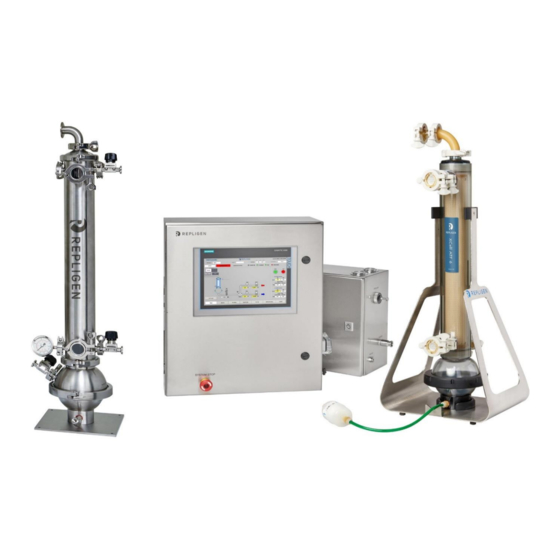
XCell
ATF System
With C410:V4B Controller
USER GUIDE
XCell ™ ATF4 | XCell ™ ATF6 | XCell ™ ATF10
Table of
Contents
Previous
Page
Next
Page
1
2
3
4
5
Advertisement
Table of Contents
Need help?
Do you have a question about the XCell ATF Series and is the answer not in the manual?
Ask a question
Questions and answers
Related Manuals for REPLIGEN XCell ATF Series
Water Filtration Systems REPLIGEN XCell ATF 2 User Manual
Stainless steel housings (25 pages)
Laboratory Equipment REPLIGEN X-Flo76 User Manual
(2 pages)
Laboratory Equipment REPLIGEN XCell ATF6 User Manual
With c410:v4b controller (126 pages)
Laboratory Equipment REPLIGEN XCell ATF10 User Manual
With c410:v4b controller (126 pages)
Laboratory Equipment REPLIGEN Spectrum KR2i User Manual And Operating Instructions
Tff systems (77 pages)
Laboratory Equipment REPLIGEN TangenX PRO PD LHV User Manual
Low holdup volume (lhv) system (14 pages)
Laboratory Equipment REPLIGEN KrosFlo TFDF User Manual
Lab system (72 pages)
Laboratory Equipment REPLIGEN KrosFlo KR2i User Manual
Tff systems (43 pages)
Laboratory Equipment REPLIGEN TangenX SIUS Cassette User Manual
(2 pages)
Laboratory Equipment REPLIGEN CTech SoloVPE PLUS User Manual
(42 pages)
Laboratory Equipment REPLIGEN TangenX PRO PD User Manual
Cassette (2 pages)
REPLIGEN TangenX PRO PD - Cassette Holder Compatibility Manual
(article)
Laboratory Equipment REPLIGEN TangenX PRO PD Compatibility Manual
Cassette holder compability (2 pages)
Laboratory Equipment REPLIGEN KrosFlo FS-15 User Manual
Rpm real-time process management system (48 pages)
Laboratory Equipment REPLIGEN KrosFlo KR2i User Manual
(47 pages)
Laboratory Equipment REPLIGEN TangenX SIUS User Manual
Auto-torque holders and system (24 pages)
This manual is also suitable for:
Xcell atf6
Xcell atf10
Xcell atf4
Table of Contents
Save PDF
Print
Rename the bookmark
Delete bookmark?
Delete from my manuals?
Login
Sign In
OR
Sign in with Facebook
Sign in with Google
Upload manual
Upload from disk
Upload from URL


Need help?
Do you have a question about the XCell ATF Series and is the answer not in the manual?
Questions and answers