Table of Contents
Advertisement
Advertisement
Table of Contents

Related Manuals for REPLIGEN KrosFlo TFDF


Summary of Contents for REPLIGEN KrosFlo TFDF
- Page 1 KrosFlo® TFDF™ Lab System User Guide IF.UG.023 R1...
- Page 2 The information contained in this document is subject to change without notice. Repligen Corporation makes no warranty of any kind with regard to this material, including, but not limited to, the implied warranties of merchantability and fitness for a particular purpose.
-
Page 3: Table Of Contents
User Guide KrosFlo® TFDF™ Lab System User Guide KrosFlo® TFDF™ Lab System Contents Optional connections ....................16 20 cm flow path installation ..................18 108 cm flow path installation ..................19 Flow path pressure sensor connections ..............21 Tubing connections ..................... 22 Pump priming set-up .................... - Page 4 User Guide KrosFlo® TFDF™ Lab System User Guide KrosFlo® TFDF™ Lab System Experimental data ....................... 44 Run Setpoints screen ....................46 Overview screen ......................49 Instrumentation ......................56 Taring .......................... 57 Pump Speed ........................ 63 Pressure/Flow ......................64 Weights ........................65 Data ..........................
- Page 5 User Guide KrosFlo® TFDF™ Lab System User Guide KrosFlo® TFDF™ Lab System List of tables Table 1. Explanation of user attention phrases .................. 9 Table 2. Explanation of symbols ......................9 Table 3. Instrument safety labels ..................... 10 Table 4. ProConnex®...
- Page 6 User Guide KrosFlo® TFDF™ Lab System User Guide KrosFlo® TFDF™ Lab System Figure 37. Concentration/Diafiltration/Concentration Mode Run Setpoints screen......48 Figure 38. Concentration Mode Overview screen ................50 Figure 39. Concentration/Diafiltration Mode Overview screen ............51 Figure 40. Concentration/Diafiltration/Concentration Mode Overview screen ........ 52 Figure 41.
- Page 7 User Guide KrosFlo® TFDF™ Lab System User Guide KrosFlo® TFDF™ Lab System Abbreviations Alternating current Conformitée Européenne Concentration Diafiltration Diafiltration volume Concentration factor Centimeter Field Application Scientist Hertz Inches Kilogram Pounds Liters/Meters /Hour Liters per minute Percent Cell Volume Pressure Sensor Proportional, Integral and Derivative Pounds per square inch Process variable...
-
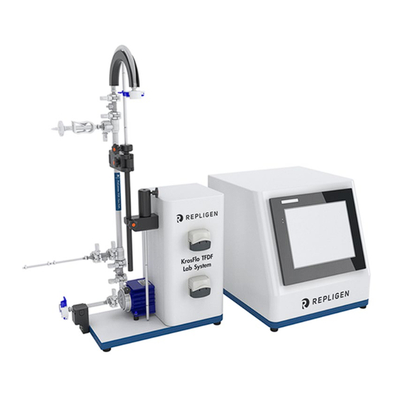
Page 8: Figure 1. Krosflo® Tfdf™ Lab System
For the latest version of the document, please visit www.repligen.com/resources. It is highly recommended that the installation process be executed by a trained Repligen engineer. For further support with troubleshooting or process optimization, please contact your local Repligen Field Application Scientist. -
Page 9: Table 1. Explanation Of User Attention Phrases
Avoid other magnets or metal parts as contamination from physical damage or cracks may arise from the magnetic attraction. Specifically pay attention to the magnetic forces when handling two pump- heads at the same time repligen.com IF.UG.023 R1... -
Page 10: Table 3. Instrument Safety Labels
Specifically pay attention to the magnetic forces when handling two pump- heads at the same time Caution Keep fingers away from rotor while pump is in operation. Stop pump before loading or unloading tubing repligen.com IF.UG.023 R1... -
Page 11: Figure 2. Krosflo® Tfdf™ Lab System Components
(bottom) transfers buffer from a diafiltration reservoir to the bioreactor during the diafiltration stage. The overall process is monitored using multiple sensors: Three in-line single-use pressure sensors for feed, permeate and retentate • • A non-invasive, clamp-on ultrasonic retentate flow meter repligen.com IF.UG.023 R1... -
Page 12: Figure 4. Pump Station
All filter sizes larger than the trial size are available as ProConnex® TFDF™ Flow Paths only, which may be configured from a library of components. Each ProConnex® TFDF™ Flow Path arrives as a fully closed, irradiated device that is ready-to-use. No flushing of the filter is required. repligen.com IF.UG.023 R1... -
Page 13: Figure 5. Proconnex® Tfdf™ Flow Path
3. Retentate pressure sensor (PE02) 4. Vent port 5. Pinch clamp 6. TFDF™ filter enclosure 7. Permeate pressure sensor (PE03) 8. Feed pressure sensor (PE01) 9. CPC AseptiQuik® genderless aseptic connector 10. Magnetic pump head 11. Ferromagnetic fixation disc repligen.com IF.UG.023 R1... -
Page 14: Figure 6. Bench Space Needed
2. Pump Station 3. Scale (for bioreactor) 4. Scale (for permeate) WARNING! The Controller weight is 36 lbs. Two people are recommended to lift the Controller out of the box and place it on the bench top. repligen.com IF.UG.023 R1... -
Page 15: Figure 8. Assembling The Stand
KrosFlo® TFDF™ Lab System Stand assembly Figure 8. Assembling the stand 5. Tubing guide rod 6. Extension rod (required only for 108 cm flow path) 7. Filter clamp 8. Sleeve 108 cm flow path configuration 20 cm flow path configuration repligen.com IF.UG.023 R1... -
Page 16: Optional Connections
Optional connections 1. Connect the 718 Minifast Turbidity sensor cable from the Pump Station to your turbidity sensor. 2. Connect the longer M12 Eurofast depth station flow meter cable from the Pump Station to your depth station. repligen.com IF.UG.023 R1... -
Page 17: Table 4. Proconnex® Tfdf™ Flow Path Specifications
3. Retentate pressure sensor (PE02) 4. Vent port 5. Pinch clamp 6. TFDF™ Filter enclosure 7. Permeate pressure sensor (PE03) 8. Feed pressure sensor (PE01) 9. CPC AseptiQuik® genderless aseptic connector 10. Magnetic pump head 11. Ferromagnetic fixation disc repligen.com IF.UG.023 R1... -
Page 18: 20 Cm Flow Path Installation
Note: Remove the ferromagnetic disc before proceeding to the next step. 20 cm flow path installation Align pump head. Pull locking pin and Rotate filter up insert pump head. (locking pin will click). repligen.com IF.UG.023 R1... -
Page 19: 108 Cm Flow Path Installation
This is much easier to during installation. connect before the flow path is installed due to its height. Note: RJ12 cables are not supplied with the ProConnex® assemblies and must be purchased separately. Note: Extender available from Repligen support. repligen.com IF.UG.023 R1... - Page 20 Pull locking pin and Rotate filter up insert pump head (locking pin will click) 7. Secure flow path with clamp and raise extension rod so that guide rod is at retentate tubing height. Make final adjustments as necessary. repligen.com IF.UG.023 R1...
-
Page 21: Flow Path Pressure Sensor Connections
PE04 to Secondary filter (OPTIONAL) • • PE05 to Guard/Sterile filter (OPTIONAL) PE06 NOT USED • Connect in-line turbidity sensor to permeate line (OPTIONAL). Note: In-line turbidity sensor cables are not supplied with the system and must be purchased separately. repligen.com IF.UG.023 R1... -
Page 22: Tubing Connections
1. Route retentate tubing over tubing guide (stand adjustments may be required). 2. Route permeate tubing through top peristaltic pump. 3. Route diafiltration buffer tubing through bottom peristaltic pump. 4. Feed line not installed in flow meter (enables easier priming). repligen.com IF.UG.023 R1... -
Page 23: Figure 13. Touchscreen Display
Turn the KrosFlo® TFDF™ Lab System on using the power switch located on the left rear panel of the main enclosure. Once the system has booted up the information screen shown below will display. Touch the screen to continue. Figure 13. Touchscreen display repligen.com IF.UG.023 R1... -
Page 24: Figure 14. Main Menu Screen
Name of screen Locks the Stops system Current time view history operations currently displayed screen operations and date Screen navigation options display on the bottom of all system screens. The options shown vary from screen to screen. repligen.com IF.UG.023 R1... -
Page 25: Figure 16. Screen Navigation
The system is programmed with a screen saver that comes on after 30 minutes of inactivity. This does not affect operation in any way. When the screen saver is active, the display will be black. Just touch the display screen to view the active system screen. repligen.com IF.UG.023 R1... -
Page 26: Pump Priming Set-Up
Retentate pressure sensor connected to PE02 Permeate pressure sensor connected to PE03 • • Vent line clamped closed • Retentate line clamped closed Feed line not installed in flow meter • • Permeate line routed through top peristaltic pump repligen.com IF.UG.023 R1... -
Page 27: Pump Priming Process
Press System Settings 3. Select peristaltic tubing size 4. Press Permeate pump P-02 flow rate Example with #13 shown Press Overview 5. Input flow rate value in mL/min 6. Press P-02 Start Press ENT Process graphic will flash green repligen.com IF.UG.023 R1... -
Page 28: Figure 18. Primed System
IMPORTANT It is critical that no fluid enters into the TFDF™ Filter element during priming. 8. Open clamp on retentate line. 9. Route feed line through flow meter. Priming is complete. Figure 18. Primed system repligen.com IF.UG.023 R1... - Page 29 Permeate continues to accumulate in the permeate reservoir. At the end of Step 2, the permeate reservoir volume reaches approximately 100% of starting cell culture volume. TMP is expected to decrease slightly. repligen.com IF.UG.023 R1...
- Page 30 Completion: Measure turbidity and product concentration in the permeate reservoir to calculate turbidity reduction and yield. Disconnect the permeate reservoir and store for the next operation. Dispose of the filter and flow path according to your internal requirements. repligen.com IF.UG.023 R1...
-
Page 31: Table 5. Sample And Process
• Can be optimized based on specific feed characteristics • > 650 LMH possible with high viability & low %PCV Diafiltration buffer volume • Volume of diafiltration buffer wash in liters • Increasing volume may reduce fouling and increase yield with challenging samples repligen.com IF.UG.023 R1... -
Page 32: Figure 19. Experiment Workflow
< 25%, reduction of the flux rate should be considered. If the %PCV is greater than 25%, trials with either early diafiltration or an initial dilution are potential steps towards improvement. If early diafiltration is implemented, recommended starting parameters are running in C/D mode with a concentration factor between 1 - 1.5. repligen.com IF.UG.023 R1... -
Page 33: Figure 20. Information Screen
System Settings: Allows the user to set pressure units, calibration factors, and max RPM of • the main pump Alarm Set-up: Allows the user to set audible alarms and stop alarm setpoints • PID Set-up: Allows the user to change PID values for main pump and aux pumps • repligen.com IF.UG.023 R1... -
Page 34: Figure 21. Main Menu Screen
The Admin screen allows users to adjust default tubing calibration factors, change the system serial number and update the permeate flow meter installation status. To access this screen, select the Admin Screen button in the Main Menu screen. repligen.com IF.UG.023 R1... -
Page 35: Changing The Default Tubing Calibration Factors
System Settings screen. For more information, see the System Settings Screen section. Changing the system serial number Select Serial # and enter the new system serial number. Once the number is updated, the new value will display under Serial #. repligen.com IF.UG.023 R1... -
Page 36: Updating The Permeate Flow Meter Installation Status
2. Select a circle button under the P-02 or P-03 Tube Size column to view size options. The button will turn green. 3. Options to select from will automatically start with #13 tubing. Select the desired tubing size. repligen.com IF.UG.023 R1... -
Page 37: Scaling
1. Select the Reset Tubing Calibration button. 2. Select YES to set the tubing calibration factors back to factory default settings. Figure 24. Reset Tubing Calibration Note: Default tubing calibration factor settings can be set in the admin screen. repligen.com IF.UG.023 R1... -
Page 38: Setting The Maximum Magnetic Levitating Recirculation/Feed Pump (P-01) Speed
These are dependent on the behavior of the measuring sensor, the final control element (such as a control valve), any control signal delays and the process itself. Approximate values of constants can usually be initially entered knowing the type of repligen.com IF.UG.023 R1... -
Page 39: Figure 25. Pid Loop Settings Screen
Reactor volume control and Permeate flow control. The default values are optimized for stable control and are recommended. To add or change values, select a blue box and enter a value. Figure 25. PID loop settings screen repligen.com IF.UG.023 R1... -
Page 40: Alarm Set-Up Screen
7. High Feed Weight (WE-01): Used to make sure the recirculation vessel does not overfill. 8. Low Feed Weight (WE-01): Used to make sure the recirculation vessel does not run dry. 9. High Permeate Weight (WE-02) – Used to make sure the permeate vessel does not overfill. repligen.com IF.UG.023 R1... -
Page 41: Figure 27. Alarm Reset Button
It can be cleared once the system is operating below alarm conditions. Selecting the Alarm Reset button will silence the alarm and reset the flashing button. Figure 27. Alarm Reset button repligen.com IF.UG.023 R1... -
Page 42: Alarm History
The Lock option on the KrosFlo® TFDF™ System allows users to lock the screen for cleaning without inadvertently affecting system operation. 1. Select Lock in the menu bar. The following message will display: Figure 29. Lock screen message 2. Select Yes. The Lock Screen will display: repligen.com IF.UG.023 R1... -
Page 43: Figure 30. Lock Screen
When the data is logging, the USB Ready button will be green and display “On”. When the data is writing, the USB Writing button will be green display “On” for a short time. When data logging is repligen.com IF.UG.023 R1... -
Page 44: Experimental Data
(Current feed wt – Perm. Hold-up)) Diafiltration volume (DV) calculation: (Permeate total – Perm wt at start of D mode) / • (Starting vol. - (Feed wt at start – Feed wt at start of D mode)) repligen.com IF.UG.023 R1... -
Page 45: Figure 33. Recorded Data Example
4. Manual Mode: Open mode where the user can start/stop any pump(s), tare scales, sensors. repligen.com IF.UG.023 R1... -
Page 46: Run Setpoints Screen
Figure 35. Concentration Mode Run Setpoints screen Concentration/Diafiltration Mode: Run Setpoints screen is used to configure a drawdown • followed by a buffer addition step, users can also use Concentration Factor (CF) or Permeate Weight as the end point for the Concentration step repligen.com IF.UG.023 R1... -
Page 47: Figure 36. Concentration/Diafiltration Mode Run Setpoints Screen
Start Concentration/Diafiltration/Concentration button in this mode initiates the Wizard feature that automatically runs calculations to determine various setpoints, for more information, refer to the Wizard feature section repligen.com IF.UG.023 R1... -
Page 48: Figure 37. Concentration/Diafiltration/Concentration Mode Run Setpoints Screen
P-03 to keep the mass at the target weight, tare with the empty product vessel so only the weight of the sample is read, the target should then be the weight of the sample once the recirculation line is filled Diafiltration setpoint values (Concentration/Diafiltration and Concentration/Diafiltration/ Concentration modes): repligen.com IF.UG.023 R1... -
Page 49: Overview Screen
User input of Concentration Factor or Permeate weight for Concentration step • Change direction of Auxiliary pumps (P-02 and P-03) Tare scales (WE-01 and WE-02) • • Tare pressure sensors (PE-01, PE-02, PE-03, PE-04, PE-05, and PE-06) Tare Flow meter (FL-01 and FL-02) • repligen.com IF.UG.023 R1... -
Page 50: Figure 38. Concentration Mode Overview Screen
User input of Diafiltration Volume or Permeate weight for Diafiltration step Change direction of Auxiliary pumps (P-02 and P-03) • • Tare scales (WE-01 and WE-02) Tare pressure sensors (PE-01, PE-02, PE-03, PE-04, PE-05, and PE-06) • • Zero Flow meter (FL-01 and FL-02) repligen.com IF.UG.023 R1... -
Page 51: Figure 39. Concentration/Diafiltration Mode Overview Screen
User input of Concentration Factor or Permeate weight for Concentration 2 step • • Change direction of Auxiliary pumps (P-02 and P-03) Tare scales (WE-01 and WE-02) • • Tare pressure sensors (PE-01, PE-02, PE-03, PE-04, PE-05, and PE-06) • Tare Flow meter (FL-01 and FL-02) repligen.com IF.UG.023 R1... -
Page 52: Figure 40. Concentration/Diafiltration/Concentration Mode Overview Screen
Time for reference at diafiltration pump start • Time for reference at diafiltration pump stop • Time for reference at run end To run the Wizard feature: 1. Select the Start Conc./Diaf./Conc. button in the Run Setpoints screen. repligen.com IF.UG.023 R1... -
Page 53: Figure 41. Starting The Wizard Feature
Repeat this step for any other settings that need to be calculated. Note: Users can enter values for one, multiple or all settings in the Wizard feature. repligen.com IF.UG.023 R1... -
Page 54: Figure 43. Initial Wizard Feature Screen
If a Calculation Failure message displays, valid setpoint criteria could not be determined • based on the input. Adjust the entered values and restart the calculation If a Calculation Timeout message displays, select RESET and restart the calculation • To exit the Wizard feature, select Close. repligen.com IF.UG.023 R1... -
Page 55: Figure 45. Manual Mode Overview Screen
Perm Flow: Flow of permeate calculated by rpm of permeate pump VT: Volumetric Throughput - Total permeate mass/volume divided by the surface area of the • filter Perm Total: Totalized Permeate volume calculated from pump rpm • repligen.com IF.UG.023 R1... -
Page 56: Instrumentation
Note: Confirm direction of flow. For more detailed instructions about the functionality of the overview screens please refer to the System Modes section on page 45. Note: All data entered and saved in the system must be inputted in this manner repligen.com IF.UG.023 R1... -
Page 57: Taring
Select Manual in the Run Setpoints screen to change to manual mode. In manual mode, the TFDF™ setpoints will no longer be available. To operate in manual mode, return to the Overview Screen. repligen.com IF.UG.023 R1... -
Page 58: Figure 48. Manual Mode Run Setpoints Screen
Surface Area – displays the membrane surface area as calculated by inner circumference multiplied by the length of the fiber To view available filter modules and select one for the operational mode, touch the Select Module button. The Filter List Screen will display. repligen.com IF.UG.023 R1... -
Page 59: Figure 50. Filter List Screen (Left Side)
The initial table displays the Fiber Size and Fiber Count columns. To view EFF Length, select the Navigation icon and then the Right arrow to scroll in the table. repligen.com IF.UG.023 R1... -
Page 60: Figure 52. Filter List Screen (Right Side)
2. Select the Navigation icon. 3. Select the Load button. 4. Select Close. The part number for the filter module selected will now display in the filter options in the System Mode Screen and will be used during system operation. repligen.com IF.UG.023 R1... -
Page 61: Figure 53. Plot Screen
Table 13 for a list of all parameters plotted To hide the pen toolbar, toggle the arrow button on the lower left of the screen • repligen.com IF.UG.023 R1... -
Page 62: Table 7. Parameter Data
Feed pressure Psig or mbar PE-02 Retentate pressure Psig or mbar PE-03 Permeate pressure Psig or mbar P-01 Feed pump set-point RPM or LPM P-02 Pump speed P-02 RPM or ml/min P-03 Pump speed P-03 RPM or ml/min repligen.com IF.UG.023 R1... -
Page 63: Pump Speed
Pen traces in the Pump Speed plot display trend data for the following: • P-01 PID set point P-01 PID PV • • P-02 PID set point P-02 PID PV • • P-03 PID set point P-03 PD PV • Figure 54. Pump Speed plot repligen.com IF.UG.023 R1... -
Page 64: Pressure/Flow
Pen traces in the Pressure/Flow plot display trend data for the following: • PE-01 Feed pressure PE-02 Retentate pressure • • PE-03 Permeate pressure Recirc/Feed flow • • Permeate flow PE-04 Pre-sterile filter • PE-05 Post sterile filter • • FL-02 Scale flow Figure 55. Pressure/Flow plot repligen.com IF.UG.023 R1... -
Page 65: Weights
User Guide KrosFlo® TFDF™ Lab System Weights Pen traces in the Weights plot display trend data for the following: • Reactor weight Permeate weight • • Permeate total Figure 56. Weights plot repligen.com IF.UG.023 R1... -
Page 66: Data
PE-03 Permeate pressure Calculated TMP • • PE-04 Pre-sterile filter pressure PE-05 Post-sterile filter pressure • Feed Weight • • Permeate Weight Surface area • • Recirc/Feed flow • Permeate total FL-02 Scale flow • Figure 57. Data plot repligen.com IF.UG.023 R1... -
Page 67: Pid
Pen traces in the PID plot display trend data for the following: • P-01 PID set point P-01 PID PV • • P-02 PID set point P-02 PID PV • • P-03 PID set point P-03 PD PV • Figure 58. PID plot repligen.com IF.UG.023 R1... - Page 68 1. Make sure the USB drive is inserted into the USB port on the right side of the Main Enclosure. 2. If there is a USB drive in place already, try another drive. 3. Go to the Data Logging Screen and make sure it is set to record. repligen.com IF.UG.023 R1...
-
Page 69: Table 8. Warning: Product Use Limitation
The display should be cleaned with computer screen cleaner and computer screen wipes. All repairs of the system must be performed by a qualified Repligen service engineer. Opening of the system and attempted repair by the user or third party shall void the product warranty. -
Page 70: Table 9. System Output
16 lbs (7.3 kg) Pump Station dimensions 11 x 11 x 19 in (min)/39 in (max) (28 x 28 x 48/99 cm) Controller type Controller and Pump Station rating IP20 Enclosure material of construction Delrin and powder coated/anodized aluminum repligen.com IF.UG.023 R1... -
Page 71: Table 12. System Environment
• Controller-Pump Station communication cable (26 pin) • Tubing guide rod • Extension rod with locking knob • Rod sleeve with locking knob • Filter clamp with 2 locking knobs Scales Digital scales x2 Powered RS232 communication cables x2 repligen.com IF.UG.023 R1... - Page 72 Installation ......8, 19, 20, 35, 37 TMP ............7, 45 Warning ..........9, 42, 72 ............7, 32 Mode ..32, 45, 47, 48, 49, 50, 52, 55, 60, 61 Wizard ....12, 32, 33, 34, 49, 55, 56, 57 repligen.com IF.UG.023 R1...
Need help?
Do you have a question about the KrosFlo TFDF and is the answer not in the manual?
Questions and answers