Table of Contents
Advertisement
Quick Links
Advertisement
Table of Contents

Subscribe to Our Youtube Channel
Related Manuals for PXM PiXiMo 45


Summary of Contents for PXM PiXiMo 45
- Page 1 PX 178 PiXiMo 45 Driver 6x7,5 A Manual...
-
Page 2: Table Of Contents
9. Dimensions......................... 10. Technical data........................11. Declaration of conformity....................Manufacturer reserves the right to make modifications in order to improve device operation. tel.: +48 12 626 46 92 PXM s.c. fax: 12 626 46 94 ul. Przemysłowa 12 E-mail: info@pxm.pl 30-701 Kraków, Poland... -
Page 3: General Discription
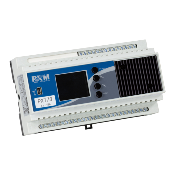
7,5 A. The PX178 driver is designed to control the LEDs. This is the most advanced device of this type available in the offer of the PXM company. The PX178 is produced in a housing of 9 standard DIN rail modules width, equipped with a color LCD screen. Thanks to that programming and control equipments operation runs more intuitively. -
Page 4: Description Of The Connectors And Control Elements
3. DESCRIPTION OF THE CONNECTORS AND CONTROL ELEMENTS Control buttons DMX-512 Input DMX-512 Output Drivers' power supply Power supply of the 1sth PWM output 1sth PWM line output USB input Display 2nd i 3rd PWM outputs with power supply lines 4-6 PWM outputs with power supply lines 4. -
Page 5: Use Of The Device
5. USE OF THE DEVICE After switching on, display shows the main menu window, which describes the current status of the PX178. Selected active settings running at this time are displayed among others drivers' received signals and the temperature of active sensors. No DMX signal is detected at the input to the device on the screen a message will... -
Page 6: Programming The Device
6. DEVICE PROGRAMMING After approving the Menu screen-button with enter button, the device's screen will display a submenu allowing you to select the available options. To program any of them you need to select the option you want and approve the choice by pressing enter You will be moved to the feature menu screen, where you can set all available parameters in the function. -
Page 7: Drivers' Working Mode
6.2. Drivers' working mode Driver mode allows to set the number of channels and their properties. Below you can find screen-shots of this submenu. Following lines represent available mode options. The device can operate in the following modes: - red, green and blue colors on 3 consecutive channels DMX-512; RGBW - red, green, blue and white on 4 consecutive channels;... -
Page 8: Channel's Balance
WWC Dyn - 2 x cool white color and warm white lamp with dimmer function on 2nd channel, in this mode up to 2 lamps can operate. 6.3. Channel's Balance This option allows you to set the maximum DMX-512 value that can be reached on each of the six DMX channels operated by the driver. -
Page 9: No Dmx Signal
6.4. No DMX Signal In this important menu you can set reaction to the lack of DMX control signal. One of the outstanding features available in this menu is the astronomical clock. It allows you to enable or disable lighting according to sunrise and sunset - setting the sunrise and sunset is parameterized by the user, you need to enter the unit location on the globe (longitude and latitude) to make this feature work properly. - Page 10 RTC Clock - astronomical clock allows switching on and off e.g. a particular program, scene, or complete of lamps according to the time of sunrise and sunset, or set by the user time. To enter the programming menu you need to select RTC clock and confirm two times with...
-
Page 11: Programs Edit
6.5. Programs Edit Programs Edit is a menu where you can set according to the needs the following parameters of programs and scenes (from which programs are composed). This option allows you to set the course of a particular program, which can be used in case of driver operation in No DMX signal mode... -
Page 12: Scenes Edit
6.6. Scenes Edit In the Scenes Edit menu, you can change settings for individual scenes. Similar to submenu Programs Edit if you select a scene that lights up a lamp or group of lamps in the case of absence of incoming DMX signal input to the controller PX178 - programmed scene is played continuously. -
Page 13: Clock And Date
To change the temperature limits for the sensor, select the appropriate button on the screen and press enter to confirm the choice. Then a new screen appears with the field where you can make a limitation of temperature. To change the temperature, follow the procedure described in the preceding sections of this instruction. -
Page 14: Screensaver
6.9. Screensaver In this menu you can activate the screen-saver mode after a time period of inactivity (not pressing the programming button in PX178). To activate this feature you need to select the Screensaver Off button and press enter . After this the box next to the text Screensaver On will be filled in. -
Page 15: Pwm Frequency
6.11. PWM frequency PWM frequency is a menu that allows you to change the refresh rate of LEDs from 287Hz to 1082Hz. Changing to a higher frequency activates a "flicker free" mode, that prevents LEDs blinking effect visible in digital cameras. This mode is particular useful anywhere where television cameras are used. - Page 16 2. MAB Time (Mark after break) is the interval time that occurs in each package according to the standard DMX-512. The minimum value is 16 microseconds. Remember to save values by selecting the button and pressing enter 3. MBF (Mark Between Frame) - the amount of time (if any)between the end of one frame (end of the 2nd stop bit) and the start of the next - Mark Time Between Frames (MTBF) is the full name.
-
Page 17: Input Dmx
6.13. Input DMX This menu provides a graphical preview of DMX-512 signal received by the device. The presentation of DMX signal: The value of DMX signal on a given channel is presented in the form white bar, the height of which varies proportionally according to the relation: the greatest height = DMX value is 255, no bar = DMX value is 0 DMX channels are described on the left side, respectively, 1, 129, 257, 385... -
Page 18: Language
6.15. Language Language Settings allow you to change the menu language. To do this select appropriate language using previous next buttons and press enter 6.16. Firmware version In this submenu you can check the firmware and bootloader version installed on the device. -
Page 19: Connection Scheme
7. CONNECTION SCHEME LED strips group PiXiMo 45 LED strips group masa DMX- DMX+ D C O K 12V DC DMX controller power PX015 Chaser Scene supply % 100 100 % Club 6p... -
Page 20: Dmx Signal Connection
In the case of using more then one power supply You should connect them between each other using "-" line, as shown on scheme below: D C O K 12V DC power supply LED strips group PiXiMo 45 LED strips group D C O K 12V DC power supply DMX SIGNAL CONNECTION PX178 have to be connected to the DMX line in series, with no branching on the control cable. -
Page 21: Dimensions
9. DIMENSIONS 60 mm 157,5 mm 10. TECHNICAL DATA - Power supply 12-24V DC - DMX input 1 (512 channels) - DMX output (512 channels) - Number of output channels - Programmable scenes - Number of programs - Control accuracy 16-bit Outputs load 7,5 A/channel... -
Page 22: Declaration Of Conformity
2004/108/WE Name of producer: PXM s.c. Address of producer: ul. Przemysłowa 12 30-701 Kraków, Poland declares that the product: Name of product: PiXiMo 45 Type: PX178 answers the following product specifications: PN-EN 61347-2-13 PN-EN 61000-6-1 PN-EN 61000-6-3 Additional information:...
Need help?
Do you have a question about the PiXiMo 45 and is the answer not in the manual?
Questions and answers