Table of Contents
Advertisement
Quick Links
Advertisement
Table of Contents

Related Manuals for PXM PX319


Summary of Contents for PXM PX319
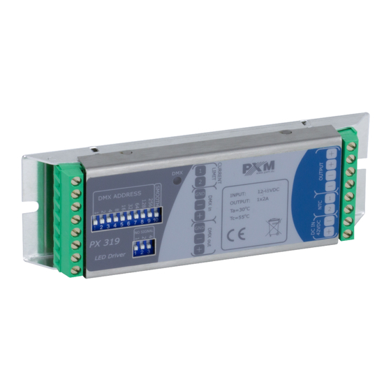
- Page 1 PX319 PX319-HV Driver LED C.C. 1 x 2A Driver LED C.C. 1 x 1,5A/hv User manual...
-
Page 2: Table Of Contents
7 DMX signal connecting................11 8 Connection scheme.................12 9 Dimensions....................13 10 Technical data..................14 Manufacturer reserves the right to make modifications in order to improve device operation. PXM Marek Żupnik sp.k. Podłęże 654 tel. +48 12 385 83 06 32-003 Podłęże mail: info@pxm.pl Rev.1-4 BDO register number 000005972 www.pxm.pl... -
Page 3: Description
LED. PX319 can be controlled by the DMX signal (the device has a built-in DMX- 512 receiver) or it can work independently. DMX address is set manually via a DIP switch on the housing. - Page 4 5. All repairs and connections of outputs or DMX signal can only be made with cut off power supply. 6. The PX319 should be strictly protected against contact with water and other liquids. 7. All sudden shocks, particularly dropping, should be avoided.
-
Page 5: Connectors And Control Elements
Connectors and control elements DMX signal LED resistor input limiting output to linear the output current LED modules DMX IN DMX OUT power supply DMX address switch temperature "No signal" and PWM frequency sensor input mode switch DMX indicator light meanings The driver is equipped with one indicator light: Status Function... -
Page 6: Dmx Address Setting
DMX address setting PX319 allows for setting the address DMX. The address is set in a binary code using the DIP Switch. Below are some examples of setting the DMX address. Nine first DIP Switches are responsible for the address; the tenth switch is responsible for activating the “smooth”... -
Page 7: Smooth Function Settings
5.2 No Signal function settings The PX319 driver is equipped with an additional DIP Switch which allows to set the No Signal function, responding to the driver action when it does not receive the DMX signal. -
Page 8: Pwm Frequency Settings
Zero brightness level and PWM frequency >20kHz Driver output current setting The PX319 driver is equipped with a function to set the output current controlling linear LED modules. Depending on the number of modules connected to the device, it is necessary to select the control current by choosing a resistor with the appropriate resistance. - Page 9 In the absence of any connection between resistor and PX319 driver, it will operate with adjusted 250mA output current (as for 100 Ω resistor connection). Below is the table allowing for the selection of resistor bar-codes: Significant Temperature Color Multiplier...
-
Page 10: Temperature Control
Example of the resistor identification : Resistor 3K - 5% - E24 1 digit tolerance multiplier 2 digit Resistor 7K5 - 1% - E96 1 digit tolerance multiplier 2 digit 6.1 Temperature control You can connect an external 4K7 thermistor to the driver. As the temperature exceeds 70°C, the driver starts to limit output power. -
Page 11: Dmx Signal Connecting
PX319 have to be connected to DMX line in serial mode, with no branches on DMX control cable. That means that DMX line, from the signal source, must be connected to DMX in pins of PX319 and later, directly from DMX out pins to the next device in DMX chain. -
Page 12: Connection Scheme
Connection scheme DMX controller resistor setting the output current for PX319 temperature sensor NTC 4K7 thermistor lamp housing to successive modules power supply 12 - 48V DC (PX319) 12 - 60V DC (PX319-HV) linear LED module linear LED module... -
Page 13: Dimensions
Dimensions 132 mm 124 mm... -
Page 14: Technical Data
10 Technical data type PX319 DMX channels 12 – 48V DC (PX319) power supply 12 – 60V DC (PX319-HV) max. power consumption 2A (PX319) / 1,5A (PX319-HV) no-load power consumption 0,5W number of output channels brightness levels of the scene 250 –... - Page 15 Podłęże, 25.11.2019 DECLARATION OF CONFORMITY PXM Marek Żupnik spółka komandytowa Podłęże 654, 32-003 Podłęże we declare that our product: Product name: Driver LED C.C. 1 x 2A Driver LED C.C. 1 x 1,5A/hv Product code: PX319 PX319-HV meets the requirements of the following standards, as well as harmonised...
Need help?
Do you have a question about the PX319 and is the answer not in the manual?
Questions and answers