Table of Contents
Advertisement
Quick Links
Advertisement
Table of Contents

Related Manuals for PXM PX178


Summary of Contents for PXM PX178
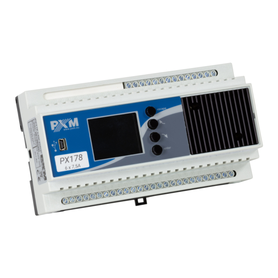
- Page 1 PX178 Driver LED C.V. 6 x 7,5A User manual...
-
Page 2: Table Of Contents
Table of Contents 1 Description....................4 2 Safety conditions..................5 3 Connectors and control elements............7 4 Navigating the menu..................8 5 Use of the device..................9 6 Device programming................10 6.1 DMX address......................11 6.2 Drivers’ working mode.....................12 6.3 Channel’s balance..................... 14 6.4 No DMX signal......................15 6.5 Program edit...................... - Page 3 Manufacturer reserves the right to make modifications in order to improve device operation. PXM Marek Żupnik sp.k. Podłęże 654 tel. +48 12 385 83 06 32-003 Podłęże mail: info@pxm.pl Rev.1-3 BDO register number 000005972 www.pxm.pl 02.02.2020...
-
Page 4: Description
Description PX178 is designed to control lamps or voltage LED strips. This is the most advanced driver of its kind offered by the PXM company. The driver has been placed in a housing with a width of 9 standard rail modules and equipped with a color display. -
Page 5: Safety Conditions
(https://pxm.pl/). Safety conditions The PX178 is a device powered with safe voltage 12 – 24V DC, however, during its installation and use the following rules must be strictly observed: 1. The device may only be connected to 12 – 24V DC current (stabilized voltage) with current-carrying capacity compatible with technical data. - Page 6 8. The device cannot be turned on in places with humidity exceeding 90%. 9. The device cannot be used in places with temperature lower than +2°C or higher than +40°C. 10. For cleaning use only a damp cloth.
-
Page 7: Connectors And Control Elements
Connectors and control elements 8 5 6 1. Programming buttons 2. DMX input 3. DMX output 4. Power supply 12 – 24V DC 5. Input power for the first PWM output 6. First PWM line output 7. USB port 8. Display 9. -
Page 8: Navigating The Menu
After that you need to save the settings before going level up, this will allow storing value in memory of the PX178. To do this, after moving to the screen button you need to push enter button. -
Page 9: Use Of The Device
T: 28.8°C inside the driverhousing Menu Other (sample) parameters settings for the No Signal mode for the PX178 : a DMX input status message No DMX Signal T: 28.8°C driver operating mode when RTC Clock... -
Page 10: Device Programming
If the device is receiving a DMX signal, a [DMX OK] message in green letters is displayed : a DMX input status message (001): 255 DMX OK (002): 000 DMX address of the first output (003): 255 DMX values at (004): 000 channel individual outputs... -
Page 11: Dmx Address
6.1 DMX address After you select the [DMX address] submenu, the screen will display the current DMX address settings for the six available channels. The values shown below are the default settings for the device. DMX address group setting DMX Address 001 DMX 001 >... -
Page 12: Drivers' Working Mode
6.2 Drivers’ working mode The [Driver mode] menu allows to set the number of DMX channels used and the method they will use to control the output channels: RGBW change mode window, after selecting the RGBWA selected operating mode, confirm with enter RGBWAX RGBD RGBWD... - Page 13 HSV – Hue Saturation Value – (white light power), the first channels is • the hue, the second is saturation and the last is the white light power 2x HSV – 2 channels of HSV mode • 2x RGB – 2 channels of RGB mode (allows for controlling two lamps at •...
-
Page 14: Channel's Balance
6.3 Channel’s balance This option allows to set control values for each of the six channels operated by the driver. You can adjust maximum brightness that the diodes can reach in a particular channel and thus set the range of colors that the lamps controlled will output. -
Page 15: No Dmx Signal
6.4 No DMX signal In this menu, you can configure the response of the device if no DMX signal is received. The astronomic clock feature is one of the options you can enable. This feature will switch on and off your lighting system according to sunrise and sunset;... - Page 16 Program 1 – this option sets one of the 8 available programs which • are programmed in the [Program Edit] menu when the driver does not detect a DMX signal at the input. To change the number of the displayed program, proceed as described in the [Scene 1] section. Channels On –...
-
Page 17: Program Edit
Astronomical Clock ON OFF Scena – – 04:34:26 Scene 02 is scheduled to be turned on 20:53:39 at 4.00 p.m. and turned off at sunrise – – – – – – Hold – after this option is selected, when the driver detects loss of •... - Page 18 XF:50% ST:5000ms Cont. Ch01:255 Ch02:000 Ch03:000 Ch04:255 Ch05:000 Ch06:000 Sc10 Ch07:000 editing the parameters of individual scenes of the program that is selected in the first column selection of one of 20 scenes (or simultaneously [ALL] ) for editing selection of a single program (or simultaneously [ALL]) for editing Scene parameters : [XF] (xfade) –...
-
Page 19: Scenes Edit
6.6 Scenes edit In the [Scene edit] menu you can change XF:50% ST:5000ms settings for individual scenes. A programmed Ch01:255 Ch02:000 Ch03:000 scene is played back continuously. The Ch04:255 Ch05:000 meanings of particular messages are described Ch06:000 Ch07:000 Sc10 Ch08:255 in the section 6.5 Program edit. -
Page 20: Date And Clock
Temperature limitation 50 °C brightness reduction trigger temperature Sensor 1 On (set within the range of 20÷70°C) 90 °C Sensor 1 Off temperature at which brightness is totally 29.1°C reduced (e.g. lamps are turned off) - set 100% within the range of 20÷90°C current temperature and power output level Minimal temperature of sensor to limit... -
Page 21: Screensaver
6.9 Screensaver This driver has a feature allowing to turn off the screen backlight. In the [Screensaver] menu, you can enable this mode after a pre-set idle time (i.e. not pressing programming buttons on the driver). To set the screensaver, confirm by pressing the enter button [Screensaver OFF] and then set the time period after which the screen backlight will be turned off. -
Page 22: Local Settings
6.10 Local settings The local settings are responsible for setting the location of your PX178 device according to geographical coordinates (longitude and latitude), and for setting the time zone in which the device operates. Time zone + – GMT+1 Longitude + –... -
Page 23: Dmx Output Settings
6.12 DMX output settings After you select the [DMX Output Settings] menu, the screen displays the current settings for DMX signal parameters. This menu allows to modify the parameters of the DMX signal being transmitted by the driver operating in the master mode. -
Page 24: Mab Time
6.12.2 MAB Time Mark After Brake is the interval time that occurs in each package according to the standard DMX512. Mark After Break Time To save the value before leaving level up Minimum 16[µs] in menu you need to select floppy disc –... -
Page 25: Packet Gap
6.12.5 Channels number Using this feature, it is possible to limit the number of channels sent from the PX178. The minimum value is 24 channels and the maximum is 512 (default). 6.13 Input DMX The [Input DMX] menu is a graphical vie of the DMX signal that is being received by the driver. -
Page 26: Internal Smooth
DMX signal presentation: The value of DMX signal in a particular DMX channel is presented as a white bar whose height varies in proportion to the following relationship: the greatest height = DMX signal value is 255; no bar = DMX signal value is 0. 6.14 Internal smooth The transition smoothing option, intended for transitions between successive control signal values, allows to make smooth transitions between... -
Page 27: Language
6.15 Language The language settings allow to change the menu language. To do this, select the appropriate language icon and confirm your selection by pressing enter. 6.16 Firmware info In this submenu you can check the firmware and bootloader version installed on the device. -
Page 28: Dmx Signal Connecting
PX178 have to be connected to DMX line in serial mode, with no branches on DMX control cable. That means that DMX line, from the signal source, must be connected to DMX IN pins of PX178 and later, directly from DMX OUT pins to the next device in DMX chain. -
Page 29: Connection Scheme
Connection scheme a) connection between LED strip group and a common power supply LED strip group LED strip group PX178 LED Driver 6x7,5A LED strip group DMX controller LED strip group e.g. PX333 power supply 12 - 24V DC... - Page 30 LED strip group and two power supply units power supply 12 - 24V DC LED strip group LED strip group PX178 LED Driver 6x7,5A LED strip group DMX controller LED strip group e.g. PX333 power supply...
-
Page 31: Dimensions
Dimensions 60 mm 158 mm... -
Page 32: Technical Data
10 Technical data type PX178 DMX channels power supply 12 – 24V DC current consumption max. 45A number of output channels control accuracy 16 bit programmable scene number of programs output load 7.5A / channel output sockets terminal blocks Master / Slave mode... - Page 33 Podłęże, 03.02.2020 DECLARATION OF CONFORMITY PXM Marek Żupnik spółka komandytowa Podłęże 654, 32-003 Podłęże we declare that our product: Product name: Driver LED C.V. 6 x 7,5A Product code: PX178 meets the requirements of the following standards, as well as harmonised...
Need help?
Do you have a question about the PX178 and is the answer not in the manual?
Questions and answers