Table of Contents
Advertisement
Quick Links
Advertisement
Table of Contents

Related Manuals for PXM PX385


Summary of Contents for PXM PX385
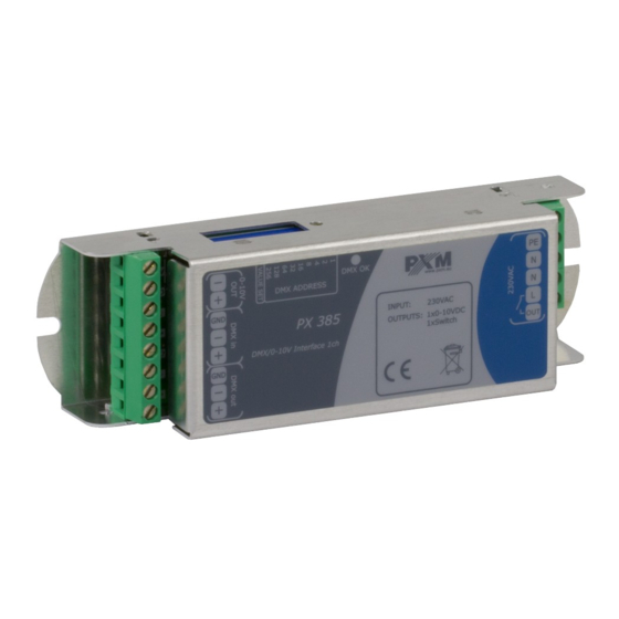
- Page 1 PX385 DMX/0-10 Interface 1ch User manual...
-
Page 2: Table Of Contents
6 Menu scheme in PX277................15 7 Connection scheme.................16 8 Dimensions....................17 9 Technical data..................17 Manufacturer reserves the right to make modifications in order to improve device operation. PXM Marek Żupnik sp.k. Podłęże 654 tel. +48 12 385 83 06 32-003 Podłęże mail: info@pxm.pl Rev.1-2 BDO register number 000005972 www.pxm.pl... -
Page 3: Description
Description The PX385 module is used to process DMX-512 signal to analogue control 1 – 10V or 1 – 10V with a relay (Relay Mode). The DMX/010 Interface 1ch has a DMX connector and 1 output voltage channel. PX385 can be controlled using a DMX signal (the device has a built-in DMX-512 signal receiver), and it can operate independently. -
Page 4: Safety Conditions
Safety conditions The PX385 is a device powered directly from power grid 230V, what may result in electric shock in case of not following safety rules. During its installation and use the following rules must be strictly observed: 1. The device should be installed as described in the manual. -
Page 5: Connectors And Control Elements
Connectors and control elements LED indicator 230V AC input analogue output DMX IN DMX OUT 230V AC output switched by a relay PX277 programmer connector DIP switch DIP switch – principle of operation : ON position 9 10 OFF position... -
Page 6: Dmx Signal Connecting
PX385 have to be connected to DMX line in serial mode, with no branches on DMX control cable. That mean that DMX line, from the signal source, must be connected to DMX in pins of PX385 and later, directly from DMX out pins to next device in DMX chain. -
Page 7: Device Configuration
Device configuration 5.1 Configuration using a DIP switch 1. Set the tenth DIP switch up (to the ON position) to enter the operating mode setup and no signal. ON position 1 2 3 4 5 6 7 8 9 10 2. -
Page 8: Configuration Using Px277
Converter settings can be changed by plugging in the PxArt+ Settings Controller. When connecting the cable to PX385, the device restarts. The main menu of the configurator allows for viewing PX385 parameters and changing the following options: brightness address, scene brightness, output mode and restoration of default parameters. -
Page 9: Description Of Information Parameters
NOTE! To change PX385 setting using the PxArt+ Settings Controller, set all DIP switches to OFF. 5.2.1 Description of information parameters Px277 controller allows to read important information Model PX385 0-10V concerning lamp to which it has been connected. They are:... -
Page 10: Scene Brightness
Scene bright. enter or escape. 255 * 5.2.4 Output modes The PX385 device can operate in two output modes: 0 – 10V • 1 – 10V – Relay mode • Using the PX277 configurator enter the submenu [Out mode] and using... - Page 11 Below is a graph describing the operation of the 1 – 10V + Relay mode. 1 - 10V controll Relay A DMX value of 0 corresponds to a voltage of 1V, with a DMX value of 25 starting to increase linearly to a value of 255. Relay switch is turned on by hysteresis, with DMX value 7 (and more), while DMX 3 value (or less) turns Relay off.
-
Page 12: Restore Default Settings
Out mode: 0-10V 5.3 RDM – description of available parameters PX385 supports the DMX-RDM protocol. DMX protocol in its assumption enables one-way data flow while its extension, the RDM protocol, can transmit information in two ways. This makes the simultaneously receiving and... - Page 13 List of RDM parameters supported by PX385: Parameter name Description SUPPORTED_PARAMETERS 0x0050 all supported parameters description of additional PARAMETER_DESCRIPTION 0x0051 parameters DEVICE_INFO 0x0060 information concerning the device SOFTWARE_VERSION_LABEL 0x00C0 firmware version of the device DMX starting address of the device;...
- Page 14 Parameter name Description device identification; two states are possible: IDENTIFY_DEVICE * 0x1000 identification is off (value 0x00) and identification is on (value 0x01) brightness settings; SCENE_BRIGHTNESS * 0x8022 Minimum value: 0, maximum value: 255. Default value is 128. * - editable parameter...
-
Page 15: Menu Scheme In Px277
Menu scheme in PX277 Model PX385 0-10V NEXT ENTER Bright. address Bright. address 001 * NEXT NEXT Bright. address Scene bright. 512 * 000 * PREV ENTER Scene bright. Scene bright. 128 * NEXT NEXT ENTER Out mode Out mode Scene bright. -
Page 16: Connection Scheme
Connection scheme 230V AC power supply fluorescent controller... -
Page 17: Dimensions
Dimensions 143,4 Technical data type PX385 power supply 230V AC number of output channels 0 – 10V output load capacity max. 10mA resistive load max. 2A, 250V AC relay output load capacity inductive load max 0.5A, 250V AC output sockets... - Page 18 Podłęże, 24.09.2019 DECLARATION OF CONFORMITY PXM Marek Żupnik spółka komandytowa Podłęże 654, 32-003 Podłęże we declare that our product: Product name: DMX/0-10 Interface 1ch Product code: PX385 meets the requirements of the following standards, as well as harmonised standards: PN-EN IEC 63000:2019-01...
Need help?
Do you have a question about the PX385 and is the answer not in the manual?
Questions and answers