Table of Contents
Advertisement
Quick Links
Advertisement
Table of Contents

Subscribe to Our Youtube Channel
Related Manuals for PXM PX292


Summary of Contents for PXM PX292
- Page 1 PX292 DMX/4-20mA Interface 8ch User manual...
-
Page 2: Table Of Contents
8 DMX signal connecting................19 9 Connection scheme.................20 10 Dimensions.....................21 11 Technical data..................21 Manufacturer reserves the right to make modifications in order to improve device operation. PXM Marek Żupnik sp.k. Podłęże 654 tel. +48 12 385 83 06 32-003 Podłęże mail: info@pxm.pl Rev.1-3 BDO register number 000005972 www.pxm.pl... -
Page 3: Description
Description PX292 is used for processing DMX-512 signal to analog 4 – 20mA. In addition to DMX signal decoding, PX292 allows to program unit reaction to loss of DMX signal. Individually programmable parameters allow for independent definition of a DMX address from the range 1 – 512 for each channel. -
Page 4: Safety Conditions
Safety conditions PX292 is a device powered by low voltage equal to 24V DC; however, please observe the following safety rules during its installation and use: 1. The device mat be connected to 24V DC with current-carrying capacity compatible with technical data. -
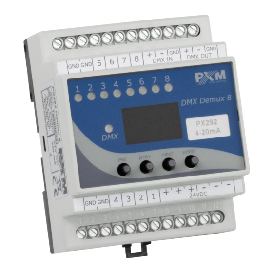
Page 5: Connectors And Control Elements
Connectors and control elements Pin no. Connection GND (-) GND (-) GND (-) GND (-) OUT 1 (+) OUT 2 (+) OUT 3 (+) OUT 4 (+) OUT 5 (+) OUT 6 (+) OUT 7 (+) OUT 8 (+) DC + power type DC + power type DC + power type DC - power type... -
Page 6: Programming
Programming After switching on, the display shows the version of the program. During the normal operation of demultiplexer, the display shows DMX address. Press enter to go the main menu, the display shows ALL. Press prev or next to select the programming menu (ALL, Ind, noS) and press enter to confirm. -
Page 7: Setting Of Dmx Address
4.1.1 Setting of DMX address PX292 menu allows to set DMX address of the device in the range from 1 to 505. In order to set DMX address: 1. Set the Adr function 2. By using next or prev set the selected DMX address. In order to accept the setting, press enter. -
Page 8: Programming Of Individual Parameters
NEXT 4.1.3 Programming of individual parameters PX292 device has the option of individual settings. It allows to assign each of the eight output channel with any DMX address. It is possible after selecting Adr. DMX address can be selected within a range from 1 to 512. -
Page 9: Response To The Loss Of Dmx Signal
4.2 Response to the loss of DMX signal This function is used both to protect the system against the disappearance of DMX signal and to gain a specific state on outputs. After it has been activated, in case of a lack of DMX signal, the module will perform the selected function by itself. - Page 10 (completely fluid transition). It is possible to reduce the number of program steps, for this purpose, for this purpose, in step which should be last and after this step followed first step, select the on option in the End menu. In each of the four scenes, you can program the values of each of the eight output channels separately in the range from 0 to 255.
-
Page 11: Smoothing Function
4.3 Smoothing function The device also has the smoothing option. Smoothing allows for smooth color changes. When this option is enabled, switching between successive DMX values sent to channels is smooth, which prevents abrupt changes in voltage. In order to start the smoothing function, enter the Sth option : 1. -
Page 12: Screen Blanking
4.4 Screen blanking The device has been equipped with the option of switching off backlight of the screen. This is provided by the SCr option. By using it, the display is switched off approx 60 seconds of inactivity (button unused). The device still operates without interfering with other parameters. -
Page 13: Default Settings And Device Errors
In such a case, try to restore the device to its default settings before sending the PX292 to the service center. If, after restoring to its default settings, the device still does not operate correctly, please send it to our service center. -
Page 14: Error Message
4.5.2 Error message The device is equipped with a built-in memory work control function. If there are problems with the memory operation on the PX292 display, the Err message appears – memory error. In this situation, select the enter key. The device will reload the default configuration and upload it to the memory. -
Page 15: Mounting
Installation on the mounting rail: 1. Set PX292 diagonally to the rail by hooking the two supports on the rear panel of the unit on the upper part of the assembly strip. 2. Pull the latch down using a screwdriver. -
Page 16: Menu Scheme
Menu scheme ENTER ENTER ENTER NEXT NEXT NEXT ENTER NEXT ENTER ENTER ENTER NEXT NEXT NEXT NEXT ENTER ENTER NEXT ENTER ENTER ENTER NEXT NEXT NEXT NEXT NEXT ENTER NEXT NEXT NEXT NEXT NEXT NEXT NEXT NEXT ENTER NEXT NEXT ENTER NEXT NEXT... -
Page 17: Rdm - Available Parameters
RDM – available parameters The PX292 supports the DMX – RDM protocol. DMX protocol allows only of a one-way data transmission, while its extension the RDM protocol can transmit information in two directions. This makes possible to simultaneously send and receive information, and hence the possibility of monitoring activities of the compatible devices. - Page 18 Parameter name Description additional device description; It is possible to enter an additional DEVICE_LABEL * 0x0082 device description using up to 32 ASCII characters FACTORY_DEFAULTS 0x0090 device default settings PERSONALITY 0x00E0 DMX operational mode PERSONALITY_ description of individual 0x00E1 DESCRIPTION operational modes selecting an option for the Smooth SMOOTH_OFF/1/2/3/4/5 *...
-
Page 19: Dmx Signal Connecting
PX292 have to be connected to DMX line in serial mode, with no branches on DMX control cable. That means that DMX line, from the signal source, must be connected to DMX IN pins of PX292 and later, directly from DMX OUT pins to the next device in DMX chain. -
Page 20: Connection Scheme
Connection scheme DMX controller e.g. PX333 4-20mA 4-20mA 4-20mA terminator DMX Demux 8 24V DC DC OK power supply 4-20mA 24 V DC 4-20mA 4-20mA... -
Page 21: Dimensions
10 Dimensions 60 mm 70 mm DMX Demux 8 24V DC 11 Technical data type PX292 power supply 24V DC number of DMX channels RDM protocol yes (from version 2.06) number of output channels output sockets screw terminals outputs load 4 –... - Page 22 Podłęże, 11.12.2020 DECLARATION OF CONFORMITY PXM Marek Żupnik spółka komandytowa Podłęże 654, 32-003 Podłęże we declare that our product: Product name: DMX/4-20mA Interface Product code: PX292 meets the requirements of the following standards, as well as harmonised standards: PN-EN IEC 63000:2019-01...
Need help?
Do you have a question about the PX292 and is the answer not in the manual?
Questions and answers