Table of Contents
Advertisement
Available languages
Available languages
Quick Links
Advertisement
Chapters
Table of Contents

Related Manuals for Chauvin Arnoux C.A 6511


Summary of Contents for Chauvin Arnoux C.A 6511
- Page 1 FR - Notice de fonctionnement GB - User’s manual DE - Bedienungsanleitung IT - Manuale d’uso ES - Manual de instrucciones C.A 6511 C.A 6513 Megohmmètres Megohmmeters Megohmmeter Megaohmmetri Megaóhmetros...
- Page 2 Deutsch ........................26 Italiano ........................38 Español ........................50 Vous venez d’acquérir un meghommètre C.A 6511 ou C.A 6513 et nous vous remercions de votre confiance. Pour obtenir le meilleur service de votre appareil : lisez attentivement cette notice de fonctionnement, ■...
-
Page 3: Table Of Contents
1.1. État de livraison ........................4 1.2. Rechange ..........................5 1.3. Mise en place des piles ....................... 5 2. PRÉSENTATION ...........................6 2.1. C.A 6511 ..........................6 2.2. C.A 6513 ..........................7 3. UTILISATION ..........................7 3.1. Précautions d'utilisation ....................... 7 3.2. Test pile ..........................8 3.3. -
Page 4: Première Mise En Service
Toute procédure de dépannage ou de vérification métrologique doit être effectuée par du personnel compétent et agréé. 1. PREMIÈRE MISE EN SERVICE 1.1. ÉTAT DE LIVRAISON Les megohmmètres C.A 6511 et C.A 6513 sont livrés dans une boîte en carton avec : ■ deux cordons de sécurité rouge et noir, ■... -
Page 5: Rechange
1.2. RECHANGE ■ Gaine antichoc ■ Lot de 10 fusibles 6,3 x 32 1,6A 660V HPC ■ Lot de 4 piles LR6 ou AA Pour les accessoires et les rechanges, consultez notre site Internet : www.chauvin-arnoux.com 1.3. MISE EN PLACE DES PILES Vérifiez qu'aucune des bornes n'est connectée et que le commutateur est bien sur OFF avant d'ouvrir l'appareil. -
Page 6: Présentation
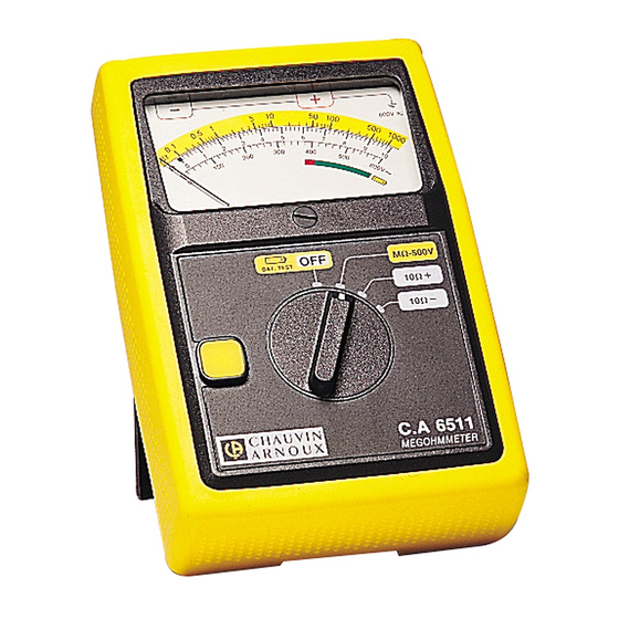
Échelle linéaire de 0 à 600 Vac pour la mesure de tension ⑤ Échelle rouge/verte pour le test pile ⑥ Vis de réglage mécanique du zéro ⑦ Commutateur rotatif de 4 positions pour le C.A 6511 et de 6 positions pour le C.A 6513. ⑧ Bouton jaune... -
Page 7: 6513
2.2. C.A 6513 3. UTILISATION 3.1. PRÉCAUTIONS D'UTILISATION ■ Au repos, l’aiguille doit indiquer 0 sur l’échelle voltmètre. Dans le cas contraire faites un réglage au moyen de la vis de réglage mécanique du zéro. ■ Positionnez le commutateur en position OFF lorsque l’appareil n’est pas utilisé. -
Page 8: Test Pile
Il est préférable que ce soit la borne + qui soit reliée à la terre. ■ À l'aide du commutateur, sélectionnez une position de mesure d'isolement : 500 V pour le C.A 6511, 500 ou 1000 V pour le C.A 6513. -
Page 9: Mesure De Résistance (C.a 6513)
3.5. MESURE DE RÉSISTANCE (C.A 6513) Après avoir relié l’appareil sur l’installation à contrôler, faites une vérification d’absence de tension (voir § 3.3). ■ Placez le commutateur sur la position 1000 Ω. La mesure se fait automatiquement sans avoir à appuyer sur le bouton jaune. -
Page 10: Variations Dans Le Domaine D'utilisation
4.2.2. MESURE DE CONTINUITÉ Domaine mesure spécifié : 0 à 10 Ω avec inversion du courant de mesure Échelle : 0 à 10 Ω Incertitude intrinsèque : 3% de la fin d'échelle Courant de court-circuit : ≥ 200 mA Tension à vide : 4,5 V ≤ V ≤ 6,5 V 4.2.3. -
Page 11: Conditions D'environnement
La consommation est d'environ : ■ 300 mA pour R = 0,5 MΩ sur le calibre MΩ 500 V ■ 600 mA pour R = 1 MΩ sur le calibre MΩ 1000 V (C.A 6513) ■ 200 mA en continuité sur les calibres +10 Ω et -10 Ω ■... -
Page 12: Conformité Aux Normes Internationales
4.8. CONFORMITÉ AUX NORMES INTERNATIONALES L’appareil est conforme selon IEC/EN 61010-2-034 ou BS EN 61010-2-034, 600 V catégorie III. Isolation double 4.9. COMPATIBILITÉ ÉLECTROMAGNÉTIQUE L’appareil est conforme selon la norme IEC/EN 61326-1 ou BS EN 61326-1. 5. MAINTENANCE Excepté les piles et le fusible, l’appareil ne comporte aucune pièce susceptible d’être remplacée par un personnel non formé... -
Page 13: Garantie
6. GARANTIE Notre garantie s’exerce, sauf stipulation expresse, pendant 24 mois après la date de mise à disposition du matériel. L’extrait de nos Conditions Générales de Vente est disponible sur notre site web. www.chauvin-arnoux.com/fr/conditions-generales-de-vente La garantie ne s’applique pas suite à : ■... - Page 14 ENGLISH Thank you for purchasing a C.A 6511 or C.A 6513 meghommeter and we thank you for your trust. For best results from your instrument: ■ read this user manual carefully, comply with the precautions for use. ■ WARNING, risk of DANGER! The operator should refer to this user’s manual whenever this danger symbol appears.
- Page 15 1.1. Delivery condition ......................16 1.2. Spare parts ........................17 1.3. Inserting the batteries ......................17 2. PRESENTATION .........................18 2.1. C.A 6511 ........................... 18 2.2. C.A 6513 ........................... 19 3. USE ...............................19 3.1. Precautions for use ......................19 3.2. Battery test ........................20 3.3.
-
Page 16: First Use
All troubleshooting and metrological checks must be performed by competent and accredited personnel. 1. FIRST USE 1.1. DELIVERY CONDITION The C.A 6511 and C.A 6513 megohmmeters are delivered in a cardboard box with : ■ two safety leads black and red, ■... -
Page 17: Spare Parts
1.2. SPARE PARTS ■ Protecting sheath ■ Set of 10 fuses 6,3 x 32 1,6A 660V HPC ■ Set of 4 LR6 or AA batteries. For the accessories and spares, consult our web site: www.chauvin-arnoux.com 1.3. INSERTING THE BATTERIES Check that no terminals are connected and that the switch is in the OFF position before opening the instrument. -
Page 18: Presentation
Linear scale from 0 to 600 Vac for voltage measurement ⑤ Red / green scale for battery test ⑥ Screw to set mechanical zero ⑦ Rotary switch of 4 positions for the C.A 6511 and 6 positions for the C.A 6513. ⑧ Yellow button... -
Page 19: 6513
2.2. C.A 6513 3. USE 3.1. PRECAUTIONS FOR USE ■ At rest, the needle must indicate 0 on the voltmeter scale. If not, adjust it by means of the mechanical zero set screw. ■ Position the switch in the OFF position when the instrument is not used.. -
Page 20: Battery Test
It is preferable for the + terminal to be earthed. ■ Use the switch to select an insulation measurement position: 500 V for the C.A 6511, 500 or 1000V for the C.A 6513. At this point, the device automatically switches to AC voltmeter mode. It measures the voltage between the + and - terminals. -
Page 21: Resistance Measurement (C.a 6513)
3.5. RESISTANCE MEASUREMENT (C.A 6513) ■ After connecting the instrument to the installation to be tested, check that there is no voltage (see § 3.3). ■ Set the switch to the 1000 Ω position. The measurement will be taken automatically without having to press the yellow button. -
Page 22: Variations In The Domain Of Use
4.2.2. CONTINUITY MEASUREMENT Specified measurement range: 0 to 10 Ω with reversal of the measurement current Scale : 0 to 10 Ω Intrinsic uncertainty: 3% of end of scale Short-circuit current: ≥ 200 mA No-load voltage: 4,5 V ≤ V ≤ 6,5 V 4.2.3. -
Page 23: Environmental Conditions
Consumption is approximately: ■ 300 mA for R = 0,5 MΩ on the MΩ 500 V range ■ 600 mA for R = 1 MΩ on the MΩ 1000 V range (C.A 6513) ■ 200 mA on continuity on the +10 Ω and -10 Ω ranges ■... -
Page 24: Conformity To International Standards
4.8. CONFORMITY TO INTERNATIONAL STANDARDS The instrument is compliant with standard IEC/EN 61010-2-034 or BS EN 61010-2-034, 600 V category III. Double insulation 4.9. ELECTROMAGNETIC COMPATIBILITY The instrument is compliant with standard IEC/EN 61326-1 or BS EN 61326-1. 5. MAINTENANCE Except for the fuse and the batteries, the instrument contains no parts that can be replaced by personnel who have not been specially trained and accredited. -
Page 25: Warranty
6. WARRANTY Except as otherwise stated, our warranty is valid for 24 months starting from the date on which the equipment was sold. The extract from our General Conditions of Sale is available on our website. www.chauvin-arnoux.com/en/general-terms-of-sale The warranty does not apply in the following cases: ■... - Page 26 DEUTSCH Sie haben einen Meghommeter C.A 6511 oder C.A 6513 erworben und wir danken Ihnen für Ihr Vertrauen. Um die optimale Benutzung Ihres Gerätes zu gewährleisten, bitten wir Sie: ■ diese Bedienungsanleitung sorgfältig zu lesen, ■ die Benutzungshinweise genau zu beachten.
- Page 27 1.1. Lieferumfang ........................28 1.2. Ersatzteile .......................... 29 1.3. Batterien Einlagen ......................29 2. VORSTELLUNG ..........................30 2.1. C.A 6511 ........................... 30 2.2. C.A 6513 ........................... 31 3. VERWENDUNG ...........................31 3.1. Vorsichtsmaßnahmen bei der Verwendung ............... 31 3.2. Batterietest ........................32 3.3.
-
Page 28: Erste Inbetriebnahme
Die Sicherheit von Systemen, in die diese Geräte eingebaut werden können, obliegt der Verantwortung des Systembauers. 1. ERSTE INBETRIEBNAHME 1.1. LIEFERUMFANG Die Megohmmeter C.A 6511 und C.A 6513 werden lieferung in Karton mit: ■ zwei Sicherheitsmessleitungen rot und schwarz, ■... -
Page 29: Ersatzteile
1.2. ERSATZTEILE ■ Schutzhülle ■ Satz von 10 Sicherungen 6,3 x 32 1,6A 660V HPC ■ Satz von 4 Batterien LR6 oder AA Für Zubehör und Ersatzteile, besuchen Sie unsere Website: www.chauvin-arnoux.com 1.3. BATTERIEN EINLAGEN Stellen Sie sicher, daß keine Prüfkabel angeschlossen sind und der Drehschalter auf OFF steht, bevor Sie das Gerät öffnen. -
Page 30: Vorstellung
Lineare Skala von 0 bis 10 Ω für Durchgangsprüfung und für Widerstandsmessung (C.A 6513) ④ Lineare Skala von 0 bis 600 Vac für Spannungsmessung ⑤ Rot/Grün Skala für Batterietest ⑥ Schraube zur mechanischen Einstellung des Nullpunkts ⑦ Drehschalter mit 4 Schaltpositionen für C.A 6511 und 6 Schaltpositionen für C.A 6513. ⑧ Gelben Schaltknopf... -
Page 31: 6513
2.2. C.A 6513 3. VERWENDUNG 3.1. VORSICHTSMASSNAHMEN BEI DER VERWENDUNG ■ Im Ruhezustand muss der Zeiger auf der Voltmeterskala 0 anzeigen. Wenn dies nicht der Fall ist, nehmen Sie eine Einstellung mithilfe der mechanischen Nullpunktschraube vor. ■ Stellen Sie den Schalter auf OFF, wenn das Gerät nicht benutzt wird. -
Page 32: Batterietest
Anlage an. Vorzugsweise sollte die + Klemme geerdet werden. ■ Wählen Sie mit dem Schalter eine Position für die Isolationsmessung: 500 V für das C.A 6511, 500 oder 1000 V für das C.A 6513. An dieser Stelle befindet sich das Gerät automatisch im Wechselspannungsmodus. Es führt eine Spannungsmessung zwischen den Anschlüssen + und - durch. -
Page 33: Widerstandsmessung (C.a 6513)
3.5. WIDERSTANDSMESSUNG (C.A 6513) ■ Nachdem du das Gerät an die zu prüfende Anlage angeschlossen hast, führe eine Prüfung auf Spannungsfreiheit durch (siehe Abs. 3.3). ■ Stelle den Schalter auf die Position 1000 Ω. Die Messung erfolgt automatisch, ohne dass du den gelben Knopf drücken musst. -
Page 34: Abweichungen Im Betriebsbereich
Loslassen des gelben Knopfes um 90 % ihres Wertes abzufallen, beträgt 1 s/μF. 4.2.2. DURCHGANGSPRÜFUNG Angegebener Messbereich: 0 bis 10 Ω mit Umkehrung des Messstroms Skala: 0 bis 10 Ω Eigenunsicherheit: 3%der vollen Skala Kurzschlussstrom: ≥ 200 mA Leerspannung: 4,5 V ≤ V ≤ 6,5 V 4.2.3. -
Page 35: Umweltbedingungen
Der Spannungsbereich, in dem eine fehlerfreie Funktion gewährleistet ist, beträgt 4,5 V bis 6,5 V. Masse des Batterien: ca. 4 x 26 g Der Stromverbrauch beträgt ungefähr: ■ 300 mA bei R = 0,5 MΩ im Messbereich MΩ 500 V ■... -
Page 36: Konformität Mit Internationalen Normen
Anschlüssen geschützt. Bei einer unabsichtlich angelegten Spannung von 1000 Vrms zwischen den Anschlüssen beträgt die Dauer des Schutzes weniger als 15 Sekunden. 4.8. KONFORMITÄT MIT INTERNATIONALEN NORMEN Das Gerät erfüllt die Norm IEC/EN 61010-2-034 bzw. BS EN 61010-2-034, 600 V Kategorie III. Doppelte Isolierung 4.9. -
Page 37: Garantie
6. GARANTIE Unsere Garantie erstreckt sich, soweit nichts anderes ausdrücklich gesagt ist, auf eine Dauer von 24 Monaten nach Überlassung des Geräts. Den Auszug aus unseren Allgemeinen Verkaufsbedingungen finden Sie auf unserer Website. www.group.chauvin-arnoux.com/de/allgemeine-geschaeftsbedingungen Eine Garantieleistung ist in folgenden Fällen ausgeschlossen: ■... - Page 38 ITALIANO Avete appena acquistato un Megaohmmetro C.A 6511 o C.A 6513. Vi ringraziamo per la vostra fiducia. Per ottenere le migliori prestazioni dal vostro strumento: ■ Leggete attentamente il presente manuale d’uso. ■ Rispettate le precauzioni d’uso. ATTENZIONE, rischio di PERICOLO! L’operatore deve consultare il presente manuale d’uso ogni volta che vedrà...
- Page 39 1.1. Caratteristiche della consegna ..................40 1.2. Ricambi ..........................41 1.3. Inserimento delle pile ......................41 2. PRESENTAZIONE ........................42 2.1. C.A 6511 ........................... 42 2.2. C.A 6513 ........................... 43 3. UTILIZZO .............................43 3.1. Precauzioni per l'uso ......................43 3.2. Collaudo pila ........................44 3.3.
-
Page 40: Prima Messa In Servizio
Ogni procedura di riparazione o di verifica metrologica va eseguita da personale competente e abilitato. 1. PRIMA MESSA IN SERVIZIO 1.1. CARATTERISTICHE DELLA CONSEGNA I megaohmmetri C.A 6511 e C.A 6513 vengono consegnati in una scatola di cartone con: ■ due cavi di sicurezza rosso e nero, ■... -
Page 41: Ricambi
1.2. RICAMBI ■ Guaina antiurto ■ Confezione di 10 fusibili 6,3 x 32 1,6A 660V HPC ■ Confezione di 4 pilas LR6 o AA Per gli accessori e i ricambi, consultare il nostro sito internet: www.chauvin-arnoux.com 1.3. INSERIMENTO DELLE PILE Verificare, prima di aprire lo strumento, che nessun morsetto sia collegato e che il commutatore sia in posizione OFF. -
Page 42: Presentazione
Scala lineare da 0 a 600 Vac per la misura di tensione ⑤ Scala rosso/verde per lo collaudo pila ⑥ Vite meccanica di regolazione dello zero ⑦ Commutatore rotativo con 4 posizioni per il C.A 6511 e 6 posizioni per il C.A 6513. ⑧ Pulsante giallo... -
Page 43: 6513
2.2. C.A 6513 3. UTILIZZO 3.1. PRECAUZIONI PER L'USO ■ A riposo, l'ago dovrebbe indicare 0 sulla scala del voltmetro. In caso contrario, utilizzare la vite di regolazione meccanica dello zero. ■ Posizionare il commutatore su OFF quando lo strumento non è in uso. -
Page 44: Collaudo Pila
È preferibile che il terminale + sia collegato a terra. ■ Utilizzare l'interruttore per selezionare una posizione di misura dell'isolamento: 500 V per il C.A 6511, 500 o 1000 V per il C.A 6513. -
Page 45: Misura Di Resistenza (C.a 6513)
3.5. MISURA DI RESISTENZA (C.A 6513) ■ Dopo aver collegato lo strumento all'impianto da testare, verificare l'assenza di tensione (vedere § 3.3). ■ Posizionare il commutatore sulla posizione 1000 Ω. La misura verrà eseguita automaticamente senza dover premere il pulsante giallo. ■... -
Page 46: Variazioni Del Campo D'utilizzo
4.2.2. MISURA DI CONTINUITÀ Campo di misura specifico: 0 a 10 Ω con inversione della corrente di misura Scala: 0 a 10 Ω Incertezza intrinseca: 3% del fondo scala Corrente di cortocircuito: ≥ 200 mA Tensione a vuoto: 4,5 V ≤ V ≤ 6,5 V 4.2.3. -
Page 47: Condizioni Ambientali
Il consumo è di circa : ■ 300 mA per R = 0,5 MΩ sul campo MΩ 500 V ■ 600 mA per R = 1 MΩ sul campo MΩ 1000 V (C.A 6513) ■ 200 mA in continuità sui campi +10 Ω e -10 Ω ■... -
Page 48: Conformità Alle Norme Internazionali
4.8. CONFORMITÀ ALLE NORME INTERNAZIONALI Lo strumento è conforme alla norma IEC/EN 61010-2-034 o BS EN 61010-2-034, 600 V categoria III. Doppio isolamento 4.9. COMPATIBILITÀ ELETTROMAGNETICA Lo strumento è conforme alla norma IEC/EN 61326-1 o BS EN 61326-1. 5. MANUTENZIONE Tranne il fusibile e le batterie (pila esclusa) lo strumento non comporta pezzi sostituibili da personale non formato e non abilitato. -
Page 49: Garanzia
6. GARANZIA Salvo stipulazione espressa la nostra garanzia si esercita, 24 mesi a decorrere dalla data di messa a disposizione del materiale. L’estratto delle nostre Condizioni Generali di Vendita è disponibile sul nostro sito Internet. www.chauvin-arnoux.com/it/condizioni-generali-di-vendita La garanzia non si applica in seguito a: ■... - Page 50 ESPAÑOL Usted acaba de adquirir un megaóhmetro C.A 6511 o C.A 6513 y le agradecemos la confianza que ha depositado en nosotros. Para conseguir las mejores prestaciones de su instrumento: ■ lea atentamente este manual de instrucciones, respete las precauciones de uso.
- Page 51 1.1. Estado de suministro ......................52 1.2. Recambios ......................... 53 1.3. Colocación de las pilas ...................... 53 2. PRESENTACIÓN .........................54 2.1. C.A 6511 ........................... 54 2.2. C.A 6513 ........................... 55 3. UTILIZACIÓN ..........................55 3.1. Precauciones de uso ......................55 3.2. Test pile ..........................56 3.3.
-
Page 52: Primera Puesta En Marcha
Cualquier reparación de avería o verificación metrológica debe efectuarse por una persona competente y autorizada. 1. PRIMERA PUESTA EN MARCHA 1.1. ESTADO DE SUMINISTRO Los megaóhmetros C.A 6511 y C.A 6513 se suministran en una caja de cartón con: ■ dos cables de seguridad rojo y negro, ■... -
Page 53: Recambios
1.2. RECAMBIOS ■ Funda de protección ■ Lote de 10 fusibles 6,3 x 32 1,6A 660V HPC ■ Lote de 4 pilas LR6 o AA Para los accesorios y los recambios, visite nuestro sitio web: www.chauvin-arnoux.com 1.3. COLOCACIÓN DE LAS PILAS Antes de abrir el instrumento, comprobar que ninguno de los bornes está... -
Page 54: Presentación
Escala lineal de 0 a 600 Vac para la medida de tensión ⑤ Escala roja/verde para el test pila ⑥ Tornillo mecánico de ajuste del cero ⑦ Conmutador rotativo de 4 posiciones para el C.A 6511 y de 6 posiciones para el C.A 6513. ⑧ Botón amarillo... -
Page 55: 6513
2.2. C.A 6513 3. UTILIZACIÓN 3.1. PRECAUCIONES DE USO ■ En reposo, la aguja debe indicar 0 en la escala del voltímetro. Si no es así, utilice el tornillo mecánico de ajuste del cero. ■ Coloque el interruptor en la posición OFF cuando no utilice el instrumento. -
Page 56: Test Pile
Es preferible que el borne + esté conectado a tierra. ■ Seleccione con el conmutador una posición de medida de aislamiento: 500 V para el C.A 6511, 500 o 1000 V para el C.A 6513. -
Page 57: Medida De Resistencia (C.a 6513)
3.5. MEDIDA DE RESISTENCIA (C.A 6513) ■ Tras conectar el instrumento a la instalación que se va a comprobar, compruebe que no haya tensión (véase § 3.3). ■ Coloque el conmutador en la posición 1000 Ω. La medida se realizará automáticamente sin necesidad de pulsar el botón amarillo. -
Page 58: Variaciones En El Rango De Utilización
90% de su valor una vez que se suelta el botón amarillo, es de 1 s/μF. 4.2.2. MEDIDA DE CONTINUIDAD Rango de medida especificado: 0 a 10 Ω con inversión de la corriente de medida Escala: 0 a 10 Ω Incertidumbre intrínseca: 3% del fin de escala Corriente de cortocircuito ≥... -
Page 59: Condiciones Ambientales
Masa de las pilas: 4 x 26 g aproximadamente El consumo es de aproximadamente: ■ 300 mA para R = 0,5 MΩ en el rango MΩ 500 V ■ 600 mA para R = 1 MΩ en el rango MΩ 1000 V (C.A 6513) ■... -
Page 60: Conformidad Con Las Normas Internacionales
4.8. CONFORMIDAD CON LAS NORMAS INTERNACIONALES El instrumento cumple con la norma IEC/EN 61010-2-034 o BS EN 61010-2-034, 600 V categoría III. Doble aislamiento 4.9. COMPATIBILIDAD ELECTROMAGNÉTICA El instrumento cumple con la norma EC/EN 61326-1 o BS EN 61326-1. 5. MANTENIMIENTO Salvo el fusible y las baterías (Salvo la pila), el instrumento no contiene ninguna pieza que pueda ser sustituida por un personal no formado y no autorizado. -
Page 61: Garantía
6. GARANTÍA Nuestra garantía tiene validez, salvo estipulación expresa, durante 24 meses a partir de la fecha de entrega del material. El extracto de nuestras Condiciones Generales de Venta está disponible en nuestro sitio Web. www.chauvin-arnoux.com/es/condiciones-generales-de-venta La garantía no se aplicará en los siguientes casos: ■... - Page 64 FRANCE INTERNATIONAL Chauvin Arnoux Chauvin Arnoux 12-16 rue Sarah Bernhardt Tél : +33 1 44 85 44 38 92600 Asnières-sur-Seine Fax : +33 1 46 27 95 69 Tél : +33 1 44 85 44 85 Fax : +33 1 46 27 73 89 Our international contacts info@chauvin-arnoux.com...
Need help?
Do you have a question about the C.A 6511 and is the answer not in the manual?
Questions and answers