Table of Contents
Advertisement
Advertisement
Table of Contents

Related Manuals for Chauvin Arnoux C.A 6522


Summary of Contents for Chauvin Arnoux C.A 6522
- Page 1 GB - User’s manual C.A 6522 C.A 6524 C.A 6526 Megohmmeters...
- Page 2 The product is declared recyclable following an analysis of the life cycle in accordance with standard ISO14040. Chauvin Arnoux has adopted an Eco-Design approach in order to design this appliance. Analysis of the complete lifecycle has enabled us to control and optimize the effects of the product on the environment. In particular this appliance exceeds regulation requirements with respect to recycling and reuse.
- Page 3 PRECAUTIONS FOR USE This instrument is compliant with safety standard IEC 61010-2-030 and the leads are compliant with IEC 61010-031, for voltages up to 600 V in category IV or 1,000 V in category III. Failure to observe the safety instructions may result in electric shock, fire, explosion, and destruction of the instrument and of the installations.
-
Page 4: Table Of Contents
CONTENTS 1. PRESENTATION ..................................5 1.1. Delivery condition ................................5 1.2. Accessories ..................................6 1.3. Replacement parts ................................. 6 1.4. Description of the instruments ............................7 1.5. Terminal block ................................11 1.6. Functions of the instrument ............................11 1.7. TEST button ................................. 11 1.8. -
Page 5: Presentation
Do not modify the leads or accessories. Any non-compliant repairs can cause risks of electric shock or burns. One C.A 6522, C.A 6524, or C.A 6526, depending on which model was ordered. Two straight/right-angle safety leads (red and black). One red crocodile clip. -
Page 6: Accessories
1.2. ACCESSORIES Type 3 remote control probe Continuity pole Thermometer + K thermocouple, C.A 861 Thermo-hygrometer C.A 846 USB-Bluetooth adapter DataView® software 1.3. REPLACEMENT PARTS 2 straight/right-angle safety leads (red and black) 1.50 m long 2 crocodile clips (red and black) 2 test probes (red and black) Carrying case that also allows hands-free use For accessories and spare parts, visit our website:... -
Page 7: Description Of The Instruments
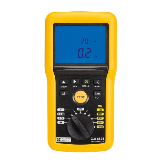
1.4. DESCRIPTION OF THE INSTRUMENTS 1.4.1. C.A 6522 Connection terminals. Backlit digital display unit. M mAµA < ALARM HOLD 4 function keys. TEST TEST button to start the measurements. Ω 250V Ω 500V 1000V Six-position switch to choose the function or to switch the instrument off. - Page 8 1.4.2. C.A 6524 Connection terminals. Backlit digital display unit. DARPI T1T2 G VHz % M mAµA < > ALARM HOLD 6 function keys. TEST TEST button to start the measurements. Ω Ω 100V Ω 250V 500V Ten-position switch to choose the function or to 1000V switch the instrument off.
- Page 9 1.4.3. C.A 6526 Connection terminals. Backlit digital display unit. DARPI T1T2 G VHz % M mAµA < > ALARM G nF µF HOLD 6 function keys. TEST TEST button to start the measurements. Ω Ω 100V Ω 250V 500V Eleven-position switch to choose the function or to MR - 1000V switch the instrument off.
- Page 10 1.4.4. ON THE BACK Captive quarter-turn screw. Battery compartment cover. Magnet for attachment to a metallic surface (for the C.A 6524 and the C.A 6526). Non-skid pads. Prop.
-
Page 11: Terminal Block
600V CAT IV 1.6. FUNCTIONS OF THE INSTRUMENT C.A 6522, C.A 6524, and C.A 6526 megohmmeters are portable measuring instruments with digital displays. They are powered by batteries. These instruments are used to check the safety of electrical installations. They are used to test new installations before they are powered up, to check an existing installation in a power-off condition, or again to troubleshoot an installation. -
Page 12: Function Keys
1.8. FUNCTION KEYS In general, the keys have a first function, marked on the key, obtained by a short press, and a second function, marked under the key, obtained by a long press. Function The TIMER key is used to select the , PI, and DAR functions. -
Page 13: Use
2. USE 2.1. GENERAL At start-up, the instrument indicates the remaining battery If the battery voltage is too low to ensure correct operation life. of the instrument, it so reports. G VHz The batteries must then be replaced (see § 4.2), since the battery life indication is no longer reliable. -
Page 14: Insulation Measurement
2.3. INSULATION MEASUREMENT Ω Set the switch to one of the MΩ positions. Ω 100V Ω 250V The test voltage you should choose depends on the voltage of the installation to be tested. For example, for a network installation at 230 V, insulation measurements 500V will be made at 500 V. - Page 15 2.3.1. OPERATION OF THE TEST BUTTON The TEST button is pressed to make an insulation measurement. The test voltage is generated for as long as the press is maintained. When the button is released, the measurement stops. mode, simply press the TEST button once to start the measurement, then press it a second time to stop; there is no In the need to keep the button pressed.
- Page 16 Interpretation of the results Condition of insulation DAR < 1,25 PI < 2 Poor or even dangerous 1,25 ≤ DAR < 1,6 2 ≤ PI < 4 Good 1,6 ≤ DAR 4 ≤ PI Excellent Press the TEST key to return to the voltage measurement. TEST 2.3.3.
-
Page 17: Continuity Measurement
The standard requires that the measurements be made at 200 mA. But a current of 20 mA reduces the consumption of the instrument and so increases its battery life. The C.A 6522 can make measurements only at 200 mA. 2.4.1. COMPENSATION OF THE LEADS To ensure precise measurements, it is necessary to compensate the resistance of the measurement leads. - Page 18 2.4.2. ELIMINATION OF THE COMPENSATION OF THE LEADS To eliminate the compensation of the leads, leave the leads open and long-press the key. > 2s The display indicates the resistance of the leads and the symbol goes off. 2.4.3. MAKING A MEASUREMENT Use the leads to connect the device to be tested to the terminals of the instrument.
-
Page 19: Resistance Measurement (C.a 6524 And C.a 6526)
2.5. RESISTANCE MEASUREMENT (C.A 6524 AND C.A 6526) The resistance measurement is made with a weak current and can measure resistances up to 1000 kΩ. Set the switch to kΩ. As for a continuity measurement, connect the device to be tested to the terminals of the instrument. The device to be tested must not be live (see §... -
Page 20: Hold Function
If the measured value is less than the stored value, the display becomes negative. Pressing the key displays, in addition, the measured value as a % of the stored value. Rmeas - Rref x 100 Rref In insulation measurements, only the digital display is modified by the ∆REL. The bargraph continues to display the true measured value. -
Page 21: Set-Up
2.10. SET-UP A long press on the SET-UP key is used to enter the configuration (set-up) function of the instrument. > 2s Then use the and keys to scroll and modify the parameters. press The buzzer is active. To deactivate it, press ... -
Page 22: Alarm Function
2.11. ALARM FUNCTION On the C.A 6522, in continuity testing, pressing the TEST key activates the alarm. The symbol is displayed, along with the threshold, which is 2 Ohms. If the measurement is below this threshold and the buzzer is active, the instrument emits an audible signal. -
Page 23: Automatic Stop
On the C.A 6526, the key is green when the alarm threshold has not been crossed and red when it has. In continuity, it is the other way round. This enables the user to check the measurement at a glance. The HOLD key is also used to stop the buzzer after an alarm threshold is crossed. - Page 24 2.13.2. REREADING THE RECORDS Set the switch to MR. The instrument displays the last measurement recorded. Ω Ω 100V Ω 250V 500V MR - 1000V To see the other measurements, press the key. The record number is decremented and the corresponding To see one particular measurement, use the ...
-
Page 25: Bluetooth Communication (C.a 6526)
The record number blinks and the main display unit Then long-press the MEM key to confirm the erasure. displays CLR. > 2s Otherwise, to cancel, long press the CLR key again. 2.13.4. ERASING ALL RECORDS Repeat the record erasure procedure: „... - Page 26 symbol is displayed and the instrument waits for a message from the computer. When the link is set up, the symbol starts blinking. If your PC does not have a Bluetooth port, install a USB-Bluetooth adapter. Then, in the Windows bar, locate the Bluetooth logo, right-click on it, and choose Add a peripheral.
-
Page 27: Errors
You can then transfer recorded data from the instrument to the computer. If you turn the switch to an insulation position, you can transmit the measurements in real time. To use the MEG software, refer to its help function. To exit from the Bluetooth connection, long-press the key again, whatever the setting of the switch. -
Page 28: Resetting The Instrument
With the C.A 6524 or C.A 6526, if this occurs during a DAR or PI measurement, the instrument interrupts the measurement and displays the screen shown opposite. 2.15.3. PRESENCE OF A VOLTAGE DURING A CONTINUITY, RESISTANCE, OR CAPACITANCE MEASUREMENT If, during a continuity, resistance, or capacitance measurement, the instrument detects an external voltage in excess of 15 V (AC or DC), it interrupts the measurement and displays the screen shown opposite. -
Page 29: Technical Characteristics
± (1.5% + 1 ct) 3.2.3. INSULATION MEASUREMENT Particular reference conditions Capacitance in parallel on resistance: null Measurement ranges as a function of the model of instrument Test voltage C.A 6522 C.A 6524 C.A 6526 10kΩ - 10GΩ 10kΩ - 10GΩ 100V 20kΩ... - Page 30 Intrinsic uncertainty Test voltage (U 50V - 100V - 250V - 500V - 1,000V 4.00 - 39.99 40.0 - 399.9 400 - 3999 4.00 - 39.99 40.0 - 200.0 Specified measurement 10 - 999 kΩ and MΩ MΩ MΩ GΩ GΩ...
- Page 31 The range of operation per IEC 61557 is from 100kΩ to 2 GΩ (see § 3.4). 3.2.4. CONTINUITY MEASUREMENTS Particular reference conditions Inductance in series with the resistance: zero. Specified measurement range (without 0.00 * - 10.00 Ω 0.0 * - 100.0 Ω compensation of the leads) Resolution 10mΩ...
-
Page 32: Variation In The Range Of Use
3.2.8. STORAGE Number of records: „ 300 for the C.A 6524 „ 1300 for the C.A 6526. 3.2.9. BLUETOOTH Bluetooth 2.1 Class II Range 10 metres 3.3. VARIATION IN THE RANGE OF USE 3.3.1. VOLTAGE MEASUREMENT Influence Quantities of influence Range of influence Quantity influenced Typical... - Page 33 Influence Quantities of influence Range of influence Quantity influenced Typical Maximum 0 to 5µF at 1mA MΩ 1% + 1 ct 50V, 100V and 250V ranges 6% + 2 ct 10% + 2 ct from 10kΩ to 3 GΩ 0 to 2µF 500V and 1,000V Capacitance in parallel ranges...
-
Page 34: Intrinsic Uncertainty And Operating Uncertainty
3.4. INTRINSIC UNCERTAINTY AND OPERATING UNCERTAINTY The megohmmeters comply with standard IEC-61557, which requires that the operating uncertainty, called B, be less than 30%. √ „ In insulation measurements, B = ± ( |A| + 1.15 ² + E ² + E ²... -
Page 35: Maintenance
4. MAINTENANCE Except for the batteries, the instrument contains no parts that can be replaced by personnel who have not been specially trained and accredited. Any unauthorized repair or replacement of a part by an “equivalent” may gravely impair safety 4.1. -
Page 36: Warranty
5. WARRANTY Except as otherwise stated, our warranty is valid for 24 months starting from the date on which the equipment was sold. Extract from our General Conditions of Sale provided on request. The warranty does not apply in the following cases: „... - Page 38 FRANCE INTERNATIONAL Chauvin Arnoux Group Chauvin Arnoux Group 190, rue Championnet Tél : +33 1 44 85 44 38 75876 PARIS Cedex 18 Fax : +33 1 46 27 95 69 Tél : +33 1 44 85 44 85 Fax : +33 1 46 27 73 89 Our international contacts info@chauvin-arnoux.com...
Need help?
Do you have a question about the C.A 6522 and is the answer not in the manual?
Questions and answers