
Subscribe to Our Youtube Channel
Related Manuals for Vivo STAND-V101QW


Summary of Contents for Vivo STAND-V101QW
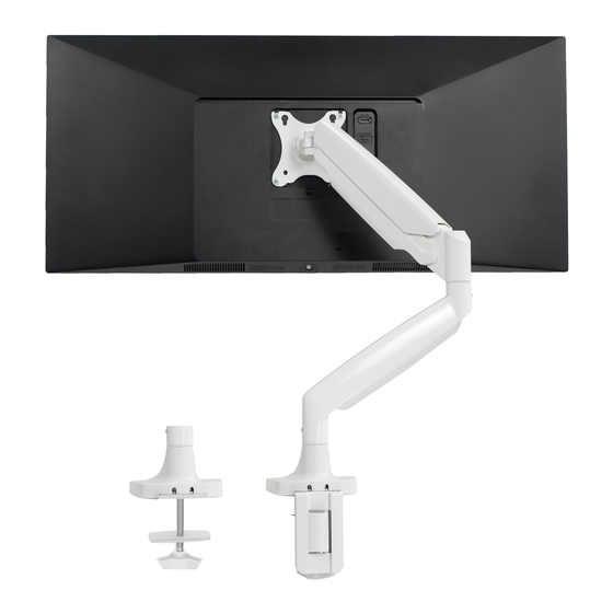
- Page 1 Pneumatic Arm Single Ultrawide Monitor Desk Mount SKU: STAND-V101Q/W Instruction Manual Assembly Video & Product Info www.vivo-us.com/products/stand-v101q...
- Page 2 If you do not understand these directions, or if you have any doubts about the safety of the installation, please contact our product support team at 309-278-5303 or help@vivo-us.com for further assistance. Check carefully to make sure there are no missing or defective parts. Improper installation may cause damage or serious injury. Do not use this product for any purpose that is not explicitly specified in this manual.
-
Page 3: Package Contents
Package Contents A (x1) B (x1) C (x1) D (x1) Uppwer Arm Lower Arm Base VESA Plate E (x1) F (x1) G (x1) Upper Clamp Lower Clamp Cover Included Hardware & Tools S-A (x4) S-B (x1) M-A (x4) M-B (x4) T-A (x1) M6x10mm Screw M8x30mm Screw... -
Page 4: Assembly Steps
ASSEMBLY STEPS STEP 1 Attach Upper Clamp (E) to underside of Base (C) using M6x10mm Screws (S-A) and 4mm Allen Wrench (T-A). Set aside. Loosen the knob on Lower Clamp (F) so that the Clamp Plate begins to lower most of the way. Clamp Plate... - Page 5 STEP 2 Option 1: Clamp Desktop Thickness 0.40” - 1.77” (10mm - 45mm) Place the Lower Clamp (F) over the loosened Flip assembly upright and loosen the pre- screws, using the keyholes, and slide down installed screws on Upper Clamp (E) by to lock into place.
- Page 6 Option 2: Clamp Desktop Thickness 1.77-3. 1 4” (45mm-80mm) Clamp Screw Clamp Bracket Use a Phillips screwdriver to remove Clamp Flip over the Clamp Bracket and reassemble Lower Screw from Lower Clamp (F) to disassemble. Clamp using a Phillips screwdriver. Loosen the pre-installed screws on Upper Place the Lower Clamp (F) over the loosened Clamp (E) by hand until there is at least 0.25”...
- Page 7 Option 3: Grommet Mount Remove Clamp Bolt (F1) and Clamp Plate Use a Phillips screwdriver to (F2) and set the other compontents aside. disassemble Lower Clamp (F). Thread Clamp Bolt (F1) into underside of Clamp Plate (F2). Place Base (C) over the grommet hole in your desktop and thread Clamp Bolt (F1) into the Base to secure.
- Page 8 STEP 3 ** READ BEFORE PROCEEDING** The Monitor Arm\ can be assembled to have a full 360° rotation or a limited 180° rotation. Follow Rotation Instructions below, then pick the rotation option that fits your setup needs. ±180° (360°) ±90° (180°) Full Rotation Limited Rotation How to Set Rotation...
- Page 9 ±180° (360°) ±90° (180°) Full Rotation Limited Rotation Fully tighten both Adjustment Screws using Loosen both Adjustment Screws using the flat the flat end on 4mm Allen Wrench (T-A). end on 4mm Allen Wrench (T-A). The screw should stick out 3/16” [4mm]. STEP 4 Slide Lower Arm (B) onto Base (C) and tighten the Set Screw on the back of Lower Arm using the flat end of 4mm Allen Wrench (T-A) to secure.
- Page 10 STEP 5 Slide the Upper Arms (A) onto Lower Arms (B) and secure together by tightening the front Lower Arm Set Screws using the flat end of 4mm Allen Wrench (T-A). Screw STEP 6 Slide VESA Plate (D) onto the head of of Upper Arms (A) and secure in place using M8x30mm Screw (S-B) and 5mm Allen Wrench (T-B).
- Page 11 STEP 7 Install two M4x12mm Screws (M-A) and M5 Washers (M-B) into the top VESA holes of each screen, leaving around 1/8” (3mm) protruding out, using a Phillips screwdriver. Then, slide the screens onto VESA Plate (D) with the screws sliding onto the VESA slots. 1/8”...
- Page 12 STEP 8 Adjusting Monitor Height Position Mount Arm Turn 10-20x to Set Monitor Height Position the arm horizontally, as shown above, and firmly hold in Turn 6mm Allen Wrench 10-20 times (T-C) place. to obtain proper support for your monitor. Use the guide below to adjust the tension according to the amount of counterbalance Insert 6mm Allen Wrench (T-C)
- Page 13 STEP 7 Route cables through Sleeves on Upper and Lower Arms (A, B). Upper Arm (A) Cable Sleeve Lower Arm (B) Cable Sleeve To remove Lower Arm Sleeve, slide the sleeve upwards. Replace when routing is complete. To remove Upper Arm Sleeve, gently pull apart.
- Page 14 Adjust as Desired Tilt Joint Adjust the tilt joint resistance on VESA Plate (D) using 6mm Allen Wrench (T-C). Swivel Adjust the swivel resistance on Upper Arm (A) using 5mm Allen Wrench (T-B). Rotation...
- Page 15 WARNING Ensure the display is alway positioned over the desk surface to prevent damage.
-
Page 16: Last Updated
LAST UPDATED: 04/25/24 REV3L STAND-V101Q v2.0 STAND-V101QW V1.0 Need Help? Get In Touch Monday-Friday from 7:00am-7:00pm CST help@vivo-us.com www.vivo-us.com 309-278-5303 Chat live with an agent! FOR MORE GREAT VIVO PRODUCTS, CHECK OUT OUR WEBSITE AT: WWW.VIVO-US.COM VIVO-us @vivo_us...
Need help?
Do you have a question about the STAND-V101QW and is the answer not in the manual?
Questions and answers