Table of Contents
Advertisement
Quick Links
Advertisement
Table of Contents

Related Manuals for Member's Mark 720-0691A


Summary of Contents for Member's Mark 720-0691A
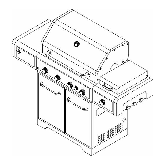
- Page 1 This Owner's Manual is provided and hosted by Appliance Factory Parts. Members Mark - Old 720-0691A - Old Owner's Manual Shop genuine replacement parts for Members Mark - Old 720-0691A - Old Find Your Members Mark - Old Grill Parts - Select From 12 Models...
- Page 2 19000272A0 This instructions manual contains important information necessary for the proper assembly and safe use of the appliance. Read and follow all warnings and instructions before assembling and using the appliance. Keep this manual for future reference. Model No: 720/730-0691A FOR OUTDOOR USE ONLY...
-
Page 3: Table Of Contents
Table of Contents Trouble Shooting ..... 23-24 Safety Instruction ..... Exploded View . -
Page 4: Safety Instruction
Safety Instruction WARNING ELECTRICAL GROUNDING INSTRUCTIONS This appliance (light and transformer) is equipped with a plug and should be plugged directly into a properly grounded receptacle. When installed, must be electrically grounded in accordance with local codes or in the absence of local codes, with the National Electrical Code, ANSI/NFPA 70 or the Canadian Electrical Code, CSA C22.1 DO NOT cut or remove the grounding prong from this plug. - Page 5 Safety Instruction continued • The gas must be turned off at the supply cylinder when the LP-Gas Supply System outdoor cooking gas appliance is not in use. • LP gas tank must be stored outdoors in a well-ventilated area Always keep the LP cylinder at 90° and out of reach of children.
- Page 6 Safety Instruction continued Use a covered hand when opening the grill lid. INSECT WARNING Never lean over an open grill. Spiders and insects can nest in the burners of this and any other grill, and cause the gas to flow improperly. This is a When lighting a burner, pay close attention to what you are very dangerous condition, which can cause a fire to occur doing.
-
Page 7: Parts Check List
Parts Check List Screws used to attach the parts are already pre-placed on the parts or grill body. Loosen the screws before you install the part. Grill Body 1 pc Side Burner Bowl 1 pc Side Shelf 1 pc Warming Rack 1 pc Control Knob 1pc Wire shelf 1pc Cooking grid 3 pcs... -
Page 8: Assembly Instruction
Assembly Instruction Tighten all screws on the grill as some screws may have loosened during transit Step 1: Side Burner Bowl Assembly Fig.1 1a). Loosen the bottom 2 screws that are located on the right side panel of the grill. Do not remove completely. - Page 9 Assembly Instruction continued Fig.3 1d). Align the bottom key holes on side burner bowl with 2 loosened screws on right side panel. Attach the side burner bowel to the cart with the two loosened screws on the side panel. See Fig.3 Tip: This step is meant to help with the installation but do not depend solely on the two screws to hold the weight of the side burner shelf.
- Page 10 Assembly Instruction continued Fig.5 Step 2: Side Shelf Assembly 2a). Loosen the bottom 2 screws that are located on the left side panel of the grill. Do not remove completely. See fig.5 2b). Remove the bottom screw that is located on the left side of control panel. See fig.5 Fig.6 2c).
- Page 11 Assembly Instruction continued Fig.7 2d). Align the bottom key holes on side shelf with 2 loosened screws on side panel. Attach the side shelf to the cart with the two loosened screws on the side panel. Hook the side shelf into the two screws. See Fig. 7 Tip: This step is meant to help with the installation but do not depend solely on the two screws to hold the weight of the side...
- Page 12 Assembly Instruction continued Fig.9 Step 3: Side Burner Valve Assembly 3a). Loosen the "C" bracket on the burner tube located on the underside of the side shelf bowl by removing the screw holding it in place. Turn the "C" bracket so the opening of the side burner tube is exposed.
- Page 13 Assembly Instruction continued Fig. 12 Step 5: Side Burner Knob Assembly 5a). Locate the small opening on the underside of the knob, behind the rubber grip and peel the rubber grip back carefully. 5b). Insert the Allen wrench into the hole and into the set screw, positioned for tightening.
- Page 14 Assembly Instruction continued Fig. 14 Step 7: Battery Assembly Unscrew the electronic igniter button and place the battery into the housing with positive terminal (+) facing outward. Replace the ignition button after the battery has been installed. See Fig. 14 Fig.
- Page 15 Liquid Propane gas supply to Natural Gas supply. Conversion kits may be purchased through www.samsclub.com For grill model #720-0691A, the NG conversion kit is model # 710-0691A. Please purchase the conversion kits appropriate for your gas grill model, and follow conversion...
-
Page 16: Gas Hook -Up
Gas Hook - Up NEVER CONNECT AN UNREGULATED GAS SUPPLY LINE TO THE APPLIANCE. USE THE REGULATOR/HOSE ASSEMBLY SUPPLIED. This is a liquid propane configured grill. Do not attempt to use a natural gas supply unless the grill has been reconfigured for natural gas use. -
Page 17: Installer Final Check List
Installer Final Check List Minimum clearance from sides and back of unit USER, PLEASE RETAIN THIS MANUAL FOR to combustible construction, 24 inches (61cm) FUTURE REFERENCE. from sides and 24 inches (61cm) from back PROPANE CYLINDER CAUTIONS All internal packaging removed. a) Do Not store a spare LP-gas cylinder under or Knobs turn freely. -
Page 18: Leak Testing
Leak Testing continued CAUTIONS Place dust cap on cylinder valve outlet when the cylinder is not in use. Only install the type of dust cap on the cylinder valve outlet that is provided with the cylinder valve. Other types of caps or plugs may result in leakage of propane. -
Page 19: Operating Instruction
Operating Instructions GENERAL USE OF THE GRILL AND ROTISSERIE NOTE: The hot grill sears the food, sealing in the juices. The more thoroughly the grill is preheated, the faster Each main burner is rated at 10,000 Btu/hr. The main the meat browns and the darker the grill marks. grill burners encompass the entire cooking area and are side ported to minimize blockage from falling DO NOT LEAVE THE GRILL UNATTENDED WHILE... -
Page 20: Lighting Instruction
Grill Lighting Instructions continued TO MATCH LIGHT THE SIDE BURNER Hold a lit extended match near the side burner ports, turn the control knob counterclockwise to “IGNITE/HI”. Move your hand immediately once the burner is lit. Rotate the control knob to the desired setting. Keep a spray bottle of soapy water near the gas supply valve and check the connections before each use. - Page 21 Lighting Instructions continued Make sure the lid is open. Push and slowly turn the Rear Burner knob to IGNITE/ON position. Keep knob pressed in until the burner is lit. Once it is lit, continue to press and hold for another 15 seconds to IGNITE / ON ensure the burner stays lit.
-
Page 22: Grill Light
Grill Light Light Operation Instruction Make sure light’s power switch on the control panel is in the “OFF” position. Connect power plug to properly grounded outlet. Turn the light’s power switch to “ON”. WARNING Keep any electrical supply cord away from any heated surface. Bulb Replacement Make sure the light’s power switch on the control panel is in the “OFF”... -
Page 23: Care And Maintenance
Care and Maintenance STAINLESS STEEL Warning: If you wish to replace main burner, we There are many different stainless steel cleaners available. strongly recommend that you hire a Always use the mildest cleaning procedure first, scrubbing in professionally trained technician to replace it. the direction of the grain. -
Page 24: Trouble Shooting
Trouble Shooting SPIDER AND INSECT WARNING Checking and cleaning burner/ venturi tubes for insects and insect nests. A clogged tube can lead to a fire beneath the grill. Spiders and small insects occasionally spin webs or make nests in the grill burner tubes during transit and warehousing. These webs can lead to gas flow obstruction which could result in a fire in and around burner tubes. - Page 25 Trouble Shooting continued PROBLEM SOLUTION When attempting to light my grill, it will Make sure you have a spark while you are trying to light the burner (if no spark) not light immediately. Ensure that the wire is connected to the electrode assembly. Clean wire (s) and / or electrode with rubbing alcohol and a clean swab.
-
Page 26: Exploded View
Exploded View... -
Page 27: Part List
Part List Warranty Warranty Part (Description) Part (Description) coverage coverage Main Lid Side shelf, Left Main Lid screw Side shelf front trim panel, left Temperature gauge Logo Main lid handle seat, left Side panel, Left Main lid handle seat, right Swivel caster with Brake Main Lid handle Swivel caster... - Page 28 Part List continued Warranty Warranty Part (Description) Part (Description) coverage coverage Rubber grommet Back panel, top Rotisserie burner igniter Cable Strainer bracket Hood Buffer B Rotisserie flex gas line Rotisserie orifice w/brass Powder cord fix bracket elbow Transformer Rotisserie igniter wire Hood Buffer A Rear baffle Lamp Cord...
-
Page 29: Ordering Parts
Ordering Parts HOW TO ORDER REPLACEMENT PARTS IMPORTANT To make sure you obtain the correct replacement part(s) Use only factory authorized parts. The use of any part for your gas grill, please refer to the parts list on pages that is not factory authorized can be dangerous. This will 26-27. - Page 30 Grill Cooking Chart continued WEIGHT OR HEAT APPROXIMATE SPECIAL INSTRUCTIONS FOOD THICKNESS SETTING TIME AND TIPS Place in aluminum foil pan. French fries Medium 15 to 30 minutes Grill, stirring occasionally Grill, turning once when juices rise to the surfaces. MEATS BEEF Medium Do not leave hamburgers unattended since a...
-
Page 31: Grill Recipe Suggestion
Grill Recipe Suggestion BBQ SALMON butter and sprinkled with chopped Combine first 4 ingredients, add onion parsley and a crisp lettuce salad. and marinade flank steak with it. 2 large salmon steaks In medium bowl, combine shrimp and Refrigerate at least 4 hours or 2 tbs. - Page 32 Grill Recipe Suggestion continued FAJITAS Bring marinade to boil on the side Marinade ribs for 3 hours. Use 1-1/2 lb. flank steak or boned chicken burner in a saucepan. Add remaining marinade for basting by adding beer breasts 1/3 c. water and peanut butter. Stir to to it.
-
Page 33: Limited Warranty
Limited Warranty Member’s Mark warrants to the original consumer-purchaser only that this product (Model #720-0691A) shall be free from defects in workmanship and materials after correct assembly and under normal and reasonable home use for the periods indicated below beginning on the date of purchase. -
Page 34: Natural Gas Conversion
Natural Gas Conversion for Model# 720-0691A 720-0691A NG Conversion Kit for Model # WARNING! FALURE TO HEED THESE WARNINGS COULD RESULT IN A FIRE OR EXPLOSION THAT COULD CAUSE SERIOUS BODILY INJURY, DEATH OR PROPERTY DAMAGE. Installation of this Natural Gas Conversion kit must be performed by a QUALIFIED GAS TECHNICIAN ONLY. - Page 35 Natural Gas Conversion for Model# 720-0691A Warning: Make sure all grill components are completely cool and gas supply is turned off and removed from grill prior to performing the conversion. NG Hose and Regulator Conversion Tools required: Phillips Head Screwdriver (+) 14mm wrench Turn all knobs to OFF.
- Page 36 Natural Gas Conversion for Model# 720-0691A Note: Make sure the orifice will be lined with valve when loose out and replace orifice in Main Tube Burner Conversion, Searing Side Burner conversion and Rear burner Conversion. And then test gas leak accordingly.
- Page 37 Natural Gas Conversion for Model# 720-0691A Searing Side Burner Conversion Tools required: Phillips Head Screwdriver (+) 6 mm Nut Driver The step-by-step instruction for converting the searing side burner’s orifice are stated below. Remove the screw under C bracket to take off the C bracket, then remove the searing side burner LP orifice with 6mm driver.
- Page 38 Natural Gas Conversion for Model# 720-0691A Rear Burner Conversion Tools required: Phillips Head Screwdriver (+) 6mm Wrench Steps: Remove the screws securing the rear baffle from inside the firebox. Remove the Rear Baffle from the back of the grill. Remove the LP orifice with 6mm wrench.
- Page 39 Natural Gas Conversion for Item# /Model# 720-0691A For Main Tube Burner Conversion Only (The 3 steps below are not necessary for the Sear side burner and Rear burner ) You will need to adjust the High Flame setting screw when converting the barbecue from Propane to Natural Gas.
- Page 40 Natural Gas Conversion for Model# 720-0691A WARNING: IMPORTANT! TO LIGHT THE SEARING SIDE BURNER BEFORE LIGHTING… To light the searing side burner, remove any cooking Inspect the gas supply hose prior to turning the gas utensils from the burner grate. Push and turn the control “ON”.
- Page 41 Natural Gas Conversion for Model# 720-0691A Note: Remove all packaging, including straps, before using the grill R ear Burner O FF O FF O FF O FF O FF O FF IG N ITE / HI IG NITE / H I...
- Page 42 Natural Gas Conversion for Model# 720-0691A Match light If the burner will not light after several attempts them the burner can be match lit, before using the match allow 5 minutes for any accumulated gas to dissipate. Clip a paper match on one end of the lighting rod.
Need help?
Do you have a question about the 720-0691A and is the answer not in the manual?
Questions and answers