Advertisement
Advertisement
Table of Contents

Subscribe to Our Youtube Channel
Related Manuals for TMG TMG-ST1845


Summary of Contents for TMG TMG-ST1845
- Page 1 Main Specifications: 0/24 TOLL FREE:1-877-761-2819 ►www.tmgindustrial.com...
-
Page 2: Main Specifications
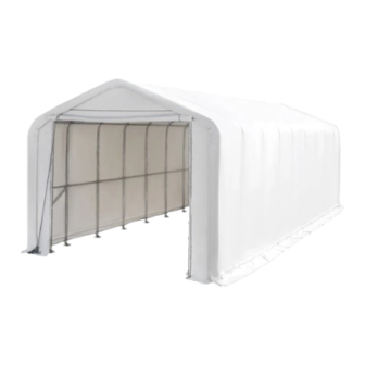
MAIN SPECIFICATIONS: Assembly size: W5.5x L13.5 x H x H5.3(m) / 18 x44.3x 17.4 (ft) Shoulder height: 4m / 13.1 ft Front roll up door: 4.09x4.26(m) / (m) / 13.4 x14 (ft) CONCRETE FOUNDATION SIZE SEE BELOW FIGURE FOUNDATION SIZE SEE BELOW FIGURE. - Page 3 The layout of foundation(two) Note: the ground anchor is installed on the the ground anchor is installed on the cement block. www.tmgindustrial.com 2/24 TOLL FREE:1 TOLL FREE:1-877-761-2819 ►www.tmgindustrial.com...
-
Page 4: Prior To Assembly
Baseplate layout. PRIOR TO ASSEMBLY Please read the instructions carefully before installation. It is important to follow your local safety regulations and industry standards during installation. Regulations may include but are not limited to: Safety helmets, protective eyewear, and clothing ... - Page 5 TMG-ST1845 PART LIST PARTS GRAPHICAL DESCRIPTION LENGTH CODE Peak arch tube L1542mm Upper rafter tube (middle trusses) L1480mm Upper rafter tube (front truss) L1480mm Upper rafter tube (rear truss) L1480mm Shoulder tube L1759mm (middle trusses and rear truss) Shoulder tube (front truss)
- Page 6 Door frame upper tube L2400mm (front truss) Rear frame middle tube L2600mm Door frame middle horizontal tube L655mm (front truss) Door frame middle horizontal tube L1782mm (rear truss) Door frame middle horizontal tube L1806mm (rear truss) Door center vertical supporting rod for L612mm cross beam (front and rear trusses) Two wheel rope pulley...
- Page 7 Half round head bolt M8 x 80mm Hex bolt M10x30mm Hex bolt M10x 50mm φ8xL15m Nylon rope φ32 Water plug Top cover W14.1xL14.7m Front cover panel W5.42xL5.46m Rear cover panel W5.42xL5.46m Braided rope φ8xL120m Ratchet straps W38xL800mm Scratch resistant tape www.tmgindustrial.com 6/24 TOLL FREE:1...
-
Page 8: Installation Steps
INSTALLATION STEPS STEP 1 : REVIEW THE WHOLE STRUCTURE AND CHOOSE THE PROPER INSTALLATION SITE STEP 1 : REVIEW THE WHOLE STRUCTURE AND CHOOSE THE PROPER INSTALLATION SITE. Mark the ground in the final building location with a line showing the positions of base plates, front doors. All Mark the ground in the final building location with a line showing the positions of base plates, front doors. - Page 9 STEP 2 : ASSEMBLE ALL TRUSSES. The building includes 10 trusses : (1) front truss, (1)rear truss, and ( trusses : (1) front truss, (1)rear truss, and (8) middle trusses. ) middle trusses. Install front truss. PART PART PART www.tmgindustrial.com 8/24...
- Page 10 Install rear truss. PART PART PART www.tmgindustrial.com 9/24 TOLL FREE:1 TOLL FREE:1-877-761-2819 ►www.tmgindustrial.com...
- Page 11 Install (8) middle trusses. PART PART PART 12x8 www.tmgindustrial.com 10/24 TOLL FREE:1 TOLL FREE:1-877-761-2819 ►www.tmgindustrial.com...
- Page 12 Lay down all (10) trusses on the ground when the assembly is all completed and before moving to next step, and then wrap (#26) around the sharp points of the joint to avoid friction between the fabric and the interface, resulting in fabric damage.
- Page 13 STEP 3: PUT UP THE FRONT TRUSS. PART PART www.tmgindustrial.com 12/24 TOLL FREE:1 TOLL FREE:1-877-761-2819 ►www.tmgindustrial.com...
- Page 14 STEP 4 : PUT UP THE REST TRUSSES. Refer to Step 3 to put up the rest trusses, connect all purlins (#5) with bolt (#17) and secure all bolts firmly on Step 3 to put up the rest trusses, connect all purlins (#5) with bolt (#17) and secure all bolts firmly on Step 3 to put up the rest trusses, connect all purlins (#5) with bolt (#17) and secure all bolts firmly on ...
- Page 15 STEP 5 : INSTALL THE DIAGONAL BRACING BARS STEP 5 : INSTALL THE DIAGONAL BRACING BARS (#13). PART PART www.tmgindustrial.com 14/24 TOLL FREE:1 TOLL FREE:1-877-761-2819 ►www.tmgindustrial.com...
- Page 16 STEP 6 : FRONT TRUSS TO COMPLETE. FRONT TRUSS TO COMPLETE. PART PART PART www.tmgindustrial.com 15/24 TOLL FREE:1 TOLL FREE:1-877-761-2819 ►www.tmgindustrial.com...
- Page 17 STEP 7 : REAR TRUSS TO COMPLETE. PART PART PART www.tmgindustrial.com 16/24 TOLL FREE:1 TOLL FREE:1-877-761-2819 ►www.tmgindustrial.com...
- Page 18 STEP 8 : INSTALL FRONT COVER PANEL The door cover must be zipped. Use rope (#24) to lift up the front and rear cover (#23) from the center grommet and tie it firm to the truss tube and spread toward both sides through each grommet along the tube. Insert the dropping tube (#15) into the bottom groove pocket on the door cover.
- Page 19 PART PART PART www.tmgindustrial.com 18/24 TOLL FREE:1 TOLL FREE:1-877-761-2819 ►www.tmgindustrial.com...
- Page 20 STEP 9 : INSTALL REAR COVER PANEL. The door cover must be zipped. Use rope (#24) to lift up the rear be zipped. Use rope (#24) to lift up the rear cover (#23A) from the center grommet and cover (#23A) from the center grommet and ...
- Page 21 STEP 10 : INSTALL THE TOP COVER . DO NOT INSTALL THE COVER DURING WINDY WEATHER! DO NOT INSTALL THE COVER DURING WINDY WEATHER! Unpack the top cover and place it along one of the long sides of the structure. Unpack the top cover and place it along one of the long sides of the structure.
- Page 22 STEP 11 : STRETCH AND TIGHTEN TOP COVER. The roof cover must be stretched and tied to the front and rear truss by rope going through the flap grommets on the cover. Start from the top center and go toward both side on each end. Add or cut the rope as needed. Pull and stretch the cover enough only to take wrinkles out.
- Page 23 STEP 12 : TENSION THE COVER ON THE STRUCTURE FROM BOTH SIDES. STEP 12 : TENSION THE COVER ON THE STRUCTURE FROM BOTH SIDES. Insert tension tubes (#14) slowly into the bottom groove pocket on both long sides. Add the water plug (#21) Insert tension tubes (#14) slowly into the bottom groove pocket on both long sides.
- Page 24 STEP 13 : INSTALL RATCHET STRAPS. Stretch and adjust the cover from left and right, back and forth, to make sure it is square and centered. Cut the Stretch and adjust the cover from left and right, back and forth, to make sure it is square and centered. Cut the Stretch and adjust the cover from left and right, back and forth, to make sure it is square and centered.
-
Page 25: After The Installation
AFTER THE INSTALLATION Walk around and inspect the shelter periodically to make sure all components are still firmly secured and the whole Walk around and inspect the shelter periodically to make sure all components are still firmly secured and the whole Walk around and inspect the shelter periodically to make sure all components are still firmly secured and the whole shelter is well supported.
Need help?
Do you have a question about the TMG-ST1845 and is the answer not in the manual?
Questions and answers