Table of Contents
Advertisement
Quick Links
Advertisement
Table of Contents

Related Manuals for SMC Networks AM20


Summary of Contents for SMC Networks AM20
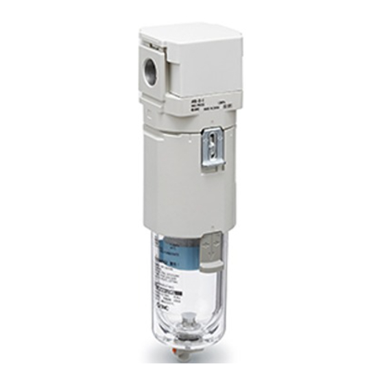
- Page 1 Mist Separator MODEL / Series / Product Number AM20-(F, N)01 ~ (F, N)02(B, C)(-2, 6, C, J, R, Z)-D AM30-(F,N)02 ~ (F, N)03(B, C, D)(-2, 6, 8, J, R, W, Z)-D AM40-(F, N)02 ~ (F, N)04(B, C, D)(-2, 6, 8, J, R, W, Z)-D...
-
Page 2: Table Of Contents
7. Assembly of Optional parts 8. Operation and Adjustment 20 to 21 9. Troubleshooting 10. Replacement work procedure 23 to 29 1) Element assembly (AM20) 23 to 24 2) Bowl assembly (AM20) 1) Element assembly (AM30/AM40) 26 to 27 2) Bowl assembly... -
Page 3: Safety Instructions
Safety Instructions These safety instructions are intended to prevent hazardous situations and/or equipment damage. These instructions indicate the level of potential hazard with the labels of “Caution,” “Warning” or “Danger.” They are all important notes for safety and must be followed in addition to International Standards (ISO/IEC) , and other safety regulations. - Page 4 Safety Instructions Caution The product is provided for use in manufacturing industries. The product herein described is basically provided for peaceful use in manufacturing industries. If considering using the product in other industries, consult SMC beforehand and exchange specifications or a contract if necessary. If anything is unclear, contact your nearest sales branch.
- Page 5 Precautions for Design Warning 1) Consult SMC if no leakage is allowed due to the environment, or if the operating fluid is not air. 2) Polycarbonate resin is used for the external parts including the bowl. Organic solvents including thinner, acetone, alcohol and ethylene chloride; chemicals including sulphuric acid, nitric acid and hydrochloric acid;...
- Page 6 5) If the air equipment is mounted on the outlet of the product, particles will be generated from the equipment and required cleanliness may not be obtained. Instead, install the air equipment at the inlet. Caution AD27-D with auto drain may have leakage of accumulated drain during pressure exhaust (this leakage is allowed in their constructions and not considered failure).
- Page 7 3) Connect piping/fittings using the recommended torque while holding the female thread side tightly. Insufficient tightening torque can cause loose piping or sealing failure. Excess tightening torque may cause damage to threads. If the female side is not held while tightening, excessive force will be applied to the bracket directly, causing breakage.
- Page 8 5) Check for dirt in resin bowl periodically. If any dirt is seen, replace with new bowl. If removing dirt by washing the resin bowl, never use washing material other than neutral detergent. Otherwise, the bowl is damaged. 6) Open and close drain cock by hand. The use of tools can result in damage to the product. 7) Replace the element before 2 years passed from start of use or pressure drop (difference between the inlet pressure and outlet pressure) reaches 0.1MPa.
-
Page 9: Application
2. Application This product aims at eliminating oil mist and solid foreign matter in the air line. 3. Standard specifications Model No. AM20 AM30 AM40 Port size 1/8, 1/4 1/4, 3/8 1/4,3/8, 1/2 Fluid Ambient and o fluid temperature -5 to 60... -
Page 10: How To Order
4. How to Order ❶ ❷ ❸ ❹ ❺ Symbol Details Body size ● ● ● ➋ Thread type ● ● ● ● ● ● ● ● ● ● ➌ Port size ● ● ● Without mounting option ● ● ●... -
Page 11: Construction / Options / Replacement Parts
5. Construction / Options / Replacement parts Note 1) Construction / Options / Replacement parts AM30/AM40 AM20 ⑤ ② ① ③ ④ Replacement parts Component number Component Parts description AM20 AM30 AM40 ① Element AM24P-060AS AM34P-060AS AM44P-060AS ② Bowl seal... -
Page 12: Bowl Assembly Specifications
6. Bowl assembly specifications 1) Bowl assembly / auto drain for AM20 Option symbol Semi-standard symbol Semi-standard: "C" Semi-standard: "-" (Standard) (Standard) Port Port ④ Part No. ④ Part No. thread thread type type C2SF-C-D C2SF-D C2SF-C(Z)-D C2SF(-Z)-D Appearance Semi-standard: "6"... - Page 13 Note 1) Note 1) Option symbol Semi-standard symbol Semi-standard: "C" Semi-standard: "-" (Standard) (Standard) Port Port ④ Part No. thread ④ Part No. thread type type AD27-C-D AD27-D AD27-C(Z)-D AD27(-Z)-D Appearance Semi-standard: "6C" and part No. Semi-standard: "6C" (Standard) (Standard) Port Port ④...
- Page 14 2) AM30 bowl assembly / auto drain Option symbol Semi-standard symbol Semi-standard: "2" Semi-standard: "-" (Standard) (Standard) Port Port ④ Part No. thread ④ Part No. thread type type C3SF-J-D C3SF-D C3SFN-J(Z)-D C3SF(-Z)-D Appearance Semi-standard: "6J" and part No. Semi-standard: "6" (Standard)...
- Page 15 Option symbol Semi-standard symbol Semi-standard: "8J" Semi-standard: "8" (Standard) (Standard) Port Port ④ Part No. thread ④ Part No. thread type type C3LF-8J-A C3LF-8-A Appearance C3LFN-8J(Z)-A C3LF-8(Z)-A and part No. Note 1) Note 1) Option symbol Semi-standard symbol Semi-standard: "-" Semi-standard: "2"...
- Page 16 Semi-standard symbol Semi-standard: "-" Semi-standard: "2" (Standard) (Standard) Port Port ④ Part No. thread ④ Part No. thread type type AD38-D AD38-2-A AD38N(-Z)-D AD38N-2(Z)- Appearance Semi-standard: "6" and part No. (Standard) Port ④ Part No. thread type AD38-6-A AD38N-6(Z)-A note 1) Option symbol Semi-standard symbol...
- Page 17 3) AM40 bowl assembly / auto drain Option symbol Semi-standard symbol Semi-standard: "J" Semi-standard: "-" (Standard) (Standard) Port Port ④ Part No. thread ④ Part No. thread type type C4SF-J-D C4SF-D C4SFN-J(Z)-D C4SF(-Z)-D Appearance and Semi-standard: "6J" part No. Semi-standard: "6" (Standard)...
- Page 18 Option symbol Semi-standard symbol Semi-standard: "8J" Semi-standard: "8" (Standard) (Standard) Port Port ④ Part No. thread ④ Part No. thread type type C4LF-8J-A C4LF-8-A Appearance and part No. C4LFN-8J(Z)-A C4LF-8(Z)-A Note 1) Note 1) Option symbol Semi-standard symbol Semi-standard: "-" Semi-standard: "2"...
- Page 19 note 1) note 1) Option symbol Semi-standard symbol Semi-standard: "-" Semi-standard: "2" (Standard) (Standard) Port Port ④ Part No. thread ④ Part No. thread type type AD48-D AD48-2-A AD48N(-Z)-D Appearance and AD48N-2(Z)-A part No. Semi-standard: "6" (Standard) Port ④ Part No. thread type AD48-6-A...
-
Page 20: Assembly Of Optional Parts
Fix the bracket B with the set screw (2pcs.) included in the package. Refer to the table below for the tightening torque. Set screw Line filter Tools Tightening torque (2 pcs.) AM20 Phillips AM30 0. 75+/-0. 2 N・m screwdriver(+) AM40 -19-... -
Page 21: Operation And Adjustment
Drain cock PUSH Drain cock (Drain discharge) Drain cock (Drain discharge) With barb fitting AM20: With drain cock (push type) AM30/AM40: Drain cock (rotation type) (Metal bowl) (Metal bowl / metal bowl with level gauge) PUSH Drain cock (Drain discharge) - Page 22 - To discharge the auto drain manually, follow the procedure below. After discharging the drain, rotate the cock to the opposite direction by hand to close the drain valve. Use of a tool can damage the product. AM30/AM40: Auto drain AM20: Auto drain OPEN (Drain discharge) Drain cock...
-
Page 23: Troubleshooting
9. Troubleshooting Refer to [10. Replacement work procedure](P23 to 29) and 11. Disassembly Drawing](P30). Problem Page for Possible causes Countermeasure reference Category Failure As pressure drop Clog of the element. Replace the element. is large, fluid does P23 to 24 Flow rate not flow. - Page 24 Before replacement, make sure that no pressure remains in the equipment. After replacement, confirm that the product satisfies specific functions and no external leakage occurs before operating it. 1.1) Element disassembly [AM20] Step 1 Step 2 Remove the joint from the product.
- Page 25 1.2) Element assembly [AM20] Step 1 Step 2 Aligh 2 arrow marks and 2 recessed areas of the joint. Press the element downward until the element and joint come into contact with each other completely. If they are forced to be inserted without aligning, the element will break.
- Page 26 1) Bowl disassembly [AM20] Step 1 Remove the bowl assembly from the product. If the bowl assembly is tightened too much to be removed, use a hook spanner until it can be loosened by hand. Body Joint Rotation ④ Bowl Assembly 2.2) Bowl assembly [AM20]...
- Page 27 3.1) Element disassembly [AM30, AM40] Step 1 Step 2 To remove the joint from the body, rotate for approx. Hold the element as shown below and pull upward to 30 degrees with the lock button held down. Align the remove the element assembly. mating mark of the body and joint and pull down the bowl assembly to remove it.
- Page 28 3.2) Element assembly - assembly [AM30, AM40] Step 1 Step 2 Aligh 2 arrow marks and 2 recessed areas of the joint. Press the element downward until the element and joint come into contact with each other completely. If they are forced to be inserted without aligning, the element will break.
- Page 29 4.1) Bowl disassembly [AM30, AM40] Step 1 To remove the bowl assembly from the product, rotate for approx. 30 degrees while the lock button is held down. Align the mating mark of the joint and bowl assembly and pull the bowl assembly down to remove it. Align the mating mark Body Mating mark of the joint...
- Page 30 4.2) Bowl assembly [AM30, AM40] Step 1 Step 2 Mount the bowl assembly at the position where the mating While the lock button is held down, rotate the bowl mark of the joint and bowl assembly meet. assembly so that the lock button meets the groove degrees of the joint (approx.
-
Page 31: Exploded Drawing
11. Disassembly Drawing 2) Exploded drawing of AM30, AM40 1) Exploded drawing of AM20 Body ① Element assembly ② Bowl seal Joint ③ Bowl seal ④ Bowl assembly -30-... -
Page 32: Dimensions
12. Dimensions (Port size) Necessary maintenance space Model Standard specifications Bracket mount AM20 1/8, 1/4 142. 3 17. 5 5. 4 8. 4 2. 3 AM30 1/4, 3/8 178. 1 21. 5 26. 5 26. 5 6. 5 2. 3 AM40 1/4・3/8・1/2... - Page 33 Revision history Revision A: September 2020 Addition of the Series 20 and 40 Revision B: September 2020 Addition of the P.6 Caution 1) 4-14-1, Sotokanda, Chiyoda-ku, Tokyo 101-0021 JAPAN Tel: + 81 3 5207 8249 Fax: +81 3 5298 5362 https://www.smcworld.com Note: Specifications are subject to change without prior notice and any obligation on the part of the manufacturer.
Need help?
Do you have a question about the AM20 and is the answer not in the manual?
Questions and answers