
Related Manuals for Epever KP Series


Summary of Contents for Epever KP Series
- Page 1 Inverter/charger User Manual KP3542-AH0650P20PS, KP3542-AH0650P20NS KP5542-AH1050P20PS, KP5542-AH1050P20NS KP5542-AH1050P20PD, KP5542-AH1050P20ND...
-
Page 2: Table Of Contents
Contents Important Safety Instructions..............1 Disclaimers....................5 1 General Information.................6 1.1 Overview............................6 1.2 Appearance...........................9 1.3 Naming rules..........................14 1.4 Connection diagram......................... 14 2 Interface....................16 2.1 Indicator............................16 2.2 Buttons............................17 2.3 Home screen..........................18 2.4 Interface............................19 2.4.1 Real-time data interface....................19 2.4.2 User interface........................ - Page 3 3.2 Wire and breaker size.......................48 3.3 Mounting the inverter/charger....................50 3.4 Wiring the inverter/charger.....................51 3.5 Operate the inverter/charger....................59 4 Working modes..................61 4.1 Abbreviation..........................61 4.2 Battery mode..........................61 4.2.1 Scenario A: Both PV and Utility are not available............61 4.2.2 Scenario B: PV is available, but the Utility is not available........62 4.2.3 Scenario C: Both PV and Utility are available..............63 4.2.4 Scenario D: The PV is not available, but the Utility is available........
-
Page 4: Important Safety Instructions
Important Safety Instructions Please reserve this manual for future review. This manual contains all the safety, installation, and operation instructions for the KP series inverter/charger ("inverter/charger" referred to as this manual). 1. Explanation of symbols To enable users to use the product efficiently and ensure personal and property safety, please read the related words carefully when you encounter the following symbols in the manual. - Page 5 4. Safety cautions before installation When receiving the inverter/charger, please check if there is any damage in transportation. If you find any problem, please contact the transportation company or CAUTION our company in time. When installing or moving the inverter/charger, follow the instructions in the manual.
- Page 6 7. Safety cautions for inverter/charger operation When the inverter/charger works, the shell will generate much heat, and the WARNING temperature is very high. Please do not touch it, and keep it far from the equipment susceptible to high temperature. SURFACE ...
- Page 7 Improper maintenance of the inverter/charger may cause personal injury or equipment damage; It is recommended to wear an antistatic wrist strap or avoid unnecessary contact with the circuit board. The safety mark, warning label, and nameplate on the inverter/charger should be visible, not removed or covered.
-
Page 8: Disclaimers
Disclaimers The warranty does not apply to the following conditions: Damage caused by improper use or inappropriate environment (it is forbidden to install the inverter/charger in humid, salt spray, corrosion, greasy, flammable, explosive, dust accumulative, or other severe environments). The actual current/voltage/power exceeds the limit value of the inverter/charger. -
Page 9: General Information
KP series, upgraded off-Grid inverter/chargers that support utility charging, oil generator charging, solar charging, utility output, inverter output, and energy management. This KP series is rich in product models, and some product models support parallel connection (12 units in standard application, more than 12 units need to be customized) in single phase and three phase, with 220VAC single phase or 380VAC three phase AC output. - Page 10 Rich product models, supporting single/dual PV input, and AC output with parallel/non-parallel. Support battery mode or non-battery mode. Non-battery mode: simultaneously charging with solar (Main) and Utility (Assist). Advanced SPWM technology and pure sine wave output. ...
- Page 11 two PV arrays connected in parallel to one access to the inverter/charger (the PV terminals of the inverter/charger need to be paralleled externally), set the "PV mode" as "ALL MULTIPLE." When there is only one PV array, the "PV mode" is "ALL SINGLE" by default, The "ALL MULTIPLE" is invalid.
-
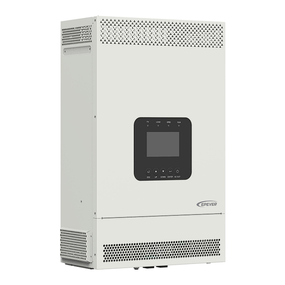
Page 12: Appearance
1.2 Appearance KP3542-AH0650P20NS/KP5542-AH1050P20NS Note: product appearance, product silk screen, terminal position KP3542-AH0650P20NS and KP5542-AH1050P20NS are the same, only the product dimensions are different. - Page 13 KP3542-AH0650P20PS/KP5542-AH1050P20PS Note: product appearance, product silk screen, terminal position KP3542-AH0650P20PS and KP5542-AH1050P20PS are the same, only the product dimensions are different.
- Page 14 KP5542-AH1050P20ND ...
- Page 15 KP5542-AH1050P20PD ❶ ❼ Instruction Instruction ⑵ ❷ ❽ Dry contact interface LCD (see chapter 3) Grounding terminal RS485 port (RJ45, with isolation...
- Page 16 RS485-A RS485-B RS485-B Please go to EPEVER official website to check or download the currently supported BMS manufacturers and the BMS parameters. (2) Dry contact specification: 1A@125VAC. Function: The dry contact interface is connected with the generator switch to turn on/off the generator.
-
Page 17: Naming Rules
Definition Definition HFS-BUS CAN-L PFS-BUS CAN-H PS-GND 6/7/8/9 Reserved 1.3 Naming rules 1.4 Connection diagram No battery mode ... - Page 18 Battery mode AC loads shall be determined according to the output power of the inverter/charger. WARNING The load exceeding the maximum output power may damage the inverter/charger. For different battery types, confirm the relevant parameters before power on. ...
-
Page 19: Interface
2 Interface Note: The display screen can be viewed clearly when the angle between the end-user's horizontal sight and the display screen is within 90°. If the angle exceeds 90°, the information on the display screen cannot be viewed clearly. 2.1 Indicator Indicator Status... -
Page 20: Buttons
2.2 Buttons Buttons Operation Instruction Exit the current interface. Click Switch from the "home screen" to the "Main Table Data Information" screen. Browse interface: Up/Down. Click Parameters setting interface: Increase or decrease the parameter value per step size. Parameters setting interface: Increase or decrease Press and hold the parameter value per 10 times the step size. -
Page 21: Home Screen
2.3 Home screen Instruction ❶ Display the system time, current battery type, and charging stage. When the BMS communication is normal, the icon will be shown on the far right, while when it is abnormal, the icon will be shown on the same position. ❷... -
Page 22: Interface
Battery voltage / battery current / lithium battery real-time SOC (display "--" without lithium battery) ❼ Parallel status icon. It shows when there is two or more inverter/chargers connect in parallel successfully, and it will not display on the single inverter/charger. ★... -
Page 24: User Interface
2.4.2 User interface After powering on the inverter/charger, the home screen shows up. Click the "ESC" button to enter the "Main Table Data Information" screen. Click the "ENTER" button to enter the next interface, or click the "UP/DOWN" button to browse the current screen display. "User Data Setup"... -
Page 25: Administrator Interface
password. The default parameters and setting range refer to chapter 2.5.1 Parameters list. 2.4.3 Administrator interface After powering on the inverter/charger, the home screen shows up. Press and hold the "ENTER" button to enter the password interface. Input the password correctly (0000 by default) to check all parameters or modify them. -
Page 26: Parameters Setting
2.5 Parameters setting 2.5.1 Parameters list Enter the "Set Data Navigation" interface according to chapter 2.4.3 Administrator interface. Then click the "UP/DOWN" button to select navigation 1-9 for detail settings. Default parameters and setting ranges are shown in the following table. Note: On the parameter setting interface, click the "UP/DOWN"... - Page 27 Parameters Default User define User define: DISABLE, ENABLE Note: The parameter will only take effect when UnbalanceSet (Current DISABLE used in three phase. After restoring to factory unbalance set) settings, the default value is the last modified value. User define:Single, Phase A, Phase B, Phase C Note: After phase set is changed, must turn off the inverter charger for 10 seconds before Phase Set...
- Page 28 Parameters Default User define In the bypass state, when the actual utility input frequency lower than this value, inverter/charger will be switched to the inverter output state. UnderFreqDisconct (Utility under 40.0Hz User define: 40.0Hz to 58.0Hz, or 40.0Hz to (Utility frequency disconnect) over frequency disconnect minus 0.5Hz), step size: 0.1Hz.
- Page 29 Parameters Default User define Under certain working modes, the utility will charge the battery if the battery voltage is lower than this Auxiliary Volt (Auxiliary value. 51.0V module ON voltage) User define: Low voltage disconnect voltage ≤ Auxiliary module ON voltage ≤ (Auxiliary module Off voltage minus (0.2*N)) (N=Rated battery voltage/12) User define:...
- Page 30 Parameters Default User define User define: DSP Auto, NoAction DSP Auto: The inverter/charger works according to BMS InvalidAction the default mode and parameters. Auto NoAction: No charging and discharging, equivalent to standby mode. It takes effect after the “ChargeControlMode” is set as “SOC.”...
- Page 31 Parameters Default User define It takes effect after the “ChargeControlMode” is set as “SOC.” UtiltyChargeOnSoc (Utility User define: 20% to 50%, or 20% to (Utility charging on Soc) charging off Soc minus 10%), step size: 1% Note: Take the minimum value between 50% and (Utility charging off Soc minus 10%).
- Page 32 Parameters Default User define Press the ENTER button to reset the self study ResetSelfStudyAH 5. Basic Param Setup User define: HAVE, NO, REV Note: When the parameter value is changed (i.e., the value is changed from “HAVE” to BAT Have (Battery have or not) HAVE “NO”, or from “NO”...
- Page 33 Parameters Default User define User define: DISABLE, ENABLE This parameter is for automatic equalizing charging. Set this value as "ENABLE," the inverter/charger performs the equalize charging automatically. After EqualizeEnable DISABLE modifying parameter restarting inverter/charger, the parameter will be restored to the default value (the previous modified value will not be saved).
- Page 34 Parameters Default User define User define: CLOSE, OPEN. Open or close the loads. This parameter and the load output switch are of the same control. To change the state of either of them, the other will be Load Open/Close OPEN changed too.
- Page 35 Parameters Default User define User define: Shared, Independent This parameter takes effect when inverter/chargers are connected in parallel. If each inverter/charger is connected to the same battery BATT Input Mode Shared pack, this value needs to be set to "Shared" mode. If each inverter/charger is connected to a separate battery pack, this value needs to be set to "Independent"...
- Page 36 Parameters Default User define User define: 0-240, step size: 1 BMS Protocol Note: Refer to the Lithium battery protocol file. BMS Com Method RS485 Read-only User define: OPEN, CLOSE Led Switch OPEN Turn on/off the PV/LOAD/GRID/RUN indicators. User define: DISABLE, ENABLE Set this value as "ENABLE,"...
- Page 37 Parameters Default User define User define: Default (25 ℃ ), BMS_ET (BMS environment temperature), BMS_C_MaxT (BMS cell maximum temperature), BMS_C_MinT (BMS cell minimum temperature), RS485, DSP The MAP table calculates the charging and discharging current values based temperature and SOC value of the lithium battery. When the lithium battery has BMS function and supports temperature upload, set “MAP TEMP TEMP...
- Page 38 Parameters Default User define FloatChagingVolt (Float charging 55.2V voltage) Read-only LowVoltReconect (Low voltage 50.0V Note: They are determined by the battery type reconnect voltage) and cannot be modified. LowVoltDisconect (Low voltage 43.2V disconnect voltage) 9. Bat Control Data Setup (This will take effect when setting the "BAT Set Mode" as "Expert" first) BAT Set Mode (Battery set Expert Read-only...
-
Page 39: Battery Work Modes
Parameters Default User define User define: (Under voltage warning voltage plus UndrVltWarnRecvr (Under 0.1*N)< Under voltage warning recover voltage≤ 48.8V voltage warning recover voltage) Low voltage reconnect voltage, step size: 0.1V Note: N=Rated battery voltage/12. User define: Discharging limit voltage≤ Under UnderVolt Warn (Under voltage voltage warning voltage<... - Page 40 1. Lithium battery pack with protective board only (no The inverter/charger controls See Figure 4 “Setting BMS) charging and discharging process for lithium battery 2. No communication based on the pre-set MAP pack with protective board (A smart remote temperature table.
- Page 41 Figure 2 “Setting process for lithium battery pack with BMS and current control function” When the system adopts a lithium battery pack with BMS and current control function at the end of charge and discharge, and the lithium battery pack can communicate with the inverter/charger normally, follow the flowchart below to set parameters correctly.
- Page 42 The inverter/charger controls charging and discharging based on the read BMS values. Please go to EPEVER official website to download the currently supported BMS manufacturers and the BMS parameters. The inverter/charger will control charging and discharging based on the LCD ...
- Page 43 Due to the different charging and discharging characteristics and voltage consistency of lithium batteries from different manufacturers, it is necessary for professionals to guide the use of VIRTUAL_BMS for charging and discharging. Figure 3 “Setting process for lithium battery pack with BMS, without current control ...
- Page 45 The inverter/charger will control charging and discharging based on the LCD settings after setting the “BMSCurent Select” as “INVALID.” Due to the different charging and discharging characteristics and voltage consistency of lithium batteries from different manufacturers, it is necessary for professionals to guide the use of VIRTUAL_BMS for charging and discharging.
- Page 46 The inverter/charger will control charging and discharging based on the LCD settings after setting the “BMSCurent Select” as “INVALID.” Due to the different charging and discharging characteristics and voltage consistency of lithium batteries from different manufacturers, it is necessary for professionals to guide the use of VIRTUAL_BMS for charging and discharging.
-
Page 47: Battery Voltage Control Parameters (Smart)
2.5.3 Battery voltage control parameters (Smart) After setting the "BAT Set Mode" as "Smart," the battery voltage control parameters are determined by the battery type and cannot be modified. To modify them, set the "BAT Set Mode" as "Expert" first. 2.5.4 Battery voltage control parameters (Expert) After setting the "BAT Set Mode"... - Page 48 2) Lithium battery voltage control parameters Battery Type LFP15S LFP16S User Define Voltage control parameters Over Voltage Disconnect Voltage 55.5V 59.2V 42.8-64V Charging Limit Voltage 54.7V 58.4V 42.8-64V Over Voltage Reconnect Voltage 54.7V 58.4V 42.8-64V Equalize Charging Voltage 53.5V 57.1V 42.8-64V Boost Charging Voltage 53.5V...
-
Page 49: Time Setting
Boost Voltage Reconnect Voltage > Low Voltage Reconnect Voltage > Low Voltage Disconnect Voltage ≥ Discharging Limit Voltage Under Voltage Warning Recover Voltage > Under Voltage Warning Voltage ≥ Discharging Limit Voltage Low Voltage Disconnect Voltage ≥ Over Discharging Protection Voltage (BMS Circuit Protection Modules) plus 0.2V The BMS circuit protection module's voltage control accuracy must be at least ±0.2V. -
Page 50: Single Installation
3 Single Installation 3.1 Attention Please read the manual carefully to familiarize yourself with the installation steps. Be very careful when installing the batteries, especially flooded lead-acid batteries. Please wear eye protection, and have fresh water available to rinse if contact with battery acid. ... -
Page 51: Wire And Breaker Size
1. The short-circuit current of the PV array must comply with the "PV Maximum Short-circuit Current" in chapter 8 Specifications. The reverse connection time should not exceed 5 minutes, avoid frequent operations in fault. 2. The PV array must first be connected to a 500VDC or above circuit breaker with arc extinguishing function, and then connected to the inverter/charger. - Page 52 When the PV modules are connected in series, the total voltage must not exceed the max. PV open circuit voltage 500V (At minimum operating environment temperature), CAUTION or 440V (At 25℃). Recommended Utility wire size Model Utility wire size Circuit breaker KP3542-AH0650P20PS /10AWG...
-
Page 53: Mounting The Inverter/Charger
The above wire and circuit breaker sizes are for reference only; please choose a suitable wire and circuit breaker according to the actual situation. 3.3 Mounting the inverter/charger Risk of explosion! Never install the inverter/charger in a sealed enclosure with flooded batteries! Do not install the inverter/charger in a confined area where the battery gas WARNING can accumulate. -
Page 54: Wiring The Inverter/Charger
Step6: Insert the screw of the M8 bolt and the steel pipe into the M10 hole. Step7: Install the inverter/charger and secure the nuts with a sleeve. 3.4 Wiring the inverter/charger Connect the inverter/charger in the order of “❶Ground > ❷Battery >... - Page 55 No battery mode ...
- Page 56 Battery mode Grounding The inverter/charger has a dedicated grounding terminal, which must be grounded reliably. The grounding wire size must be consistent with the recommended load wire size. The grounding connection...
- Page 57 point shall be as close as possible to the inverter/charger, and the total grounding wire shall be as short as possible. Do not ground the battery terminals. Do not ground the PV terminals. Do not ground the AC input L or N terminals between the inverter/charger No grounding and the household power distribution cabinet.
- Page 58 Connect the AC load Risk of electric shock! When wiring the AC load, please disconnect the circuit breaker and ensure that the poles' leads are connected correctly. The AC loads shall be determined by the continuous output power of the inverter/charger.
- Page 59 Connect the PV modules Risk of electric shock! The PV array can generate dangerous high-voltage! Disconnect the circuit breaker before wiring, and ensure that the leads of "+" and "-" poles are connected correctly. WARNING It is forbidden to connect the positive and negative poles of the PV with the ground; otherwise, the inverter/charger will be damaged.
- Page 60 Connect the Utility or generator Risk of electric shock! The Utility input can generate dangerous high-voltage! Disconnect the circuit breaker or fast-acting fuse before wiring, and ensure that the poles' leads are connected correctly. After the Utility is connected, the PV and battery cannot be grounded. In contrast, WARNING the inverter/charger cover must be grounded reliably (to shield the outside electromagnetic interference effectively and prevent the cover from causing...
- Page 61 Dry contact interface: Function: The dry contact interface can turn on/off the generator and is connected parallel with the generator's switch. Working principle: When the battery voltage reaches the Dry Contact ON Voltage, the dry contact is connected. Its coil is energized.
-
Page 62: Operate The Inverter/Charger
different battery types of the inverter charger, the default values of the Dry Contact ON Voltage and the Dry Contact OFF Voltage are different. Please refer to the chapter 2.5.1 Parameters list for details. Connect optional accessories Connect the communication module Connect the WiFi, Bluetooth, TCP, or 4G module to the RS485 com. - Page 63 Power switch Connect the battery circuit breaker first. After the inverter/charger normally works, connect the PV array and plug the utility's socket. Otherwise, we won't assume any responsibility for not following the operation. The AC output is ON by default after the inverter/charger is powered. Before WARNING turning on the power switch, ensure the AC output is connected to loads correctly, and no safety hazard exists.
-
Page 64: Working Modes
4 Working modes 4.1 Abbreviation Abbreviation Instruction PV power Load power LOAD Battery voltage Low Voltage Disconnect Voltage Low Voltage Reconnect Voltage Low Energy Disconnect SOC Low Energy Disconnect Recover SOC Auxiliary module OFF voltage (namely, Utility charging OFF voltage) Auxiliary module ON voltage (namely, Utility charging ON voltage) Utility Charging OFF SOC Utility Charging ON SOC... -
Page 65: Scenario B: Pv Is Available, But The Utility Is Not Available
❷Any of the following is satisfied, the battery stops supplying the load. The battery voltage is lower than or equal to the LVD value. The battery SOC is lower than or equal to the LED value. Set the "Charge Control Mode" as "VOLT," the working mode is determined by the battery voltage value. -
Page 66: Scenario C: Both Pv And Utility Are Available
Note: When the battery voltage is greater than or equal to the LVR value, or ❷ the battery SOC is greater than or equal to the LER value, the working mode returns to state 4.2.3 Scenario C: Both PV and Utility are available. Discharging Mode: "PV>BP>BT"... - Page 67 Charging Mode: "Solar" Discharging Mode: "BP>PV>BT" The Utility supplies power to the load, and the (C-2) PV charges the battery only. Utility Discharging Mode: "PV>BP>BT" Charging Mode: "Solar prior" ❶ When the PV power is greater than the load "PV>BT>BP"...
- Page 68 Charging Mode: "Solar prior" Discharging Mode: "BP>PV>BT" ❶ When the PV power is greater than the (MCC*V ), the Utility and PV supply power to the load, and the PV charges the battery at the same time. > MCC*V ≤ MCC*V ❷...
-
Page 69: Scenario D: The Pv Is Not Available, But The Utility Is Available
❷ When the PV power is lower than or equal to the (MCC*V ), the Utility and PV charge the battery, and the Utility supplies power to the load. Discharging Mode: No impact under any Charging Mode: "Utltyprior" mode (C-6) ... - Page 70 ❶Any of the following is satisfied, the battery Charging Mode: "Solar prior" Discharging Mode: "PV>BT>BP" supplies the load. The battery voltage is higher than or equal to the AOF value. The battery SOC is greater than or equal to (D-3)...
-
Page 71: No Battery Mode
Charging Mode: "Utly & solr" Discharging Mode: No impact under any mode or "Utltyprior" (D-5) The Utility supplies power to the load and charges Utility the battery simultaneously. 4.3 No battery mode Note: Under the no battery mode, the "Charging Mode" and "Discharging Mode" settings will not take effect. -
Page 72: Protections
5 Protections Protections Instruction When the PV array's actual charging current/power exceeds its rated current/power, it will charge the battery as per the rated current/power. When the PV voltage exceeds the bus voltage, the PV input power is constrained PV limit Current/Power by the load power, charging power, the power that the solar panels can deliver, and the current of the PV circuit breaker. - Page 73 Protections Instruction When the battery voltage goes lower than the [Low Voltage Disconnect Voltage], the battery will stop Battery over-discharge discharging to protect the battery from being over-discharged. The output is turned off immediately in the occurrence of short-circuiting. And then, the output is recovered automatically after a delay time of 5s, 10s, and 15s separately (less than three times recovery within 5 minutes, it will be recounted).
- Page 74 Protections Instruction 5350W≤P˂6295W 6295W≤P˂6995W 6995W≤P˂8500W P≥8500W KP3542-AH0650P20PS KP3542-AH0650P20NS Protect after 30 seconds Protect after 10 seconds Protect after 5 seconds Protect immediately Utility bypass overload Note: The output is recovered automatically after a delay time of 5s, 10s, and 15s separately. The (Battery mode) inverter/charger stops working after the 4th protection and can resume working after resetting or restarting.
-
Page 75: Troubleshooting
6 Troubleshooting After the inverter/charger is powered on, the meter displays the boot screen all the time (unable to enter the home screen) and the red "RUN" indicator flashes. It means the communication with the inverter/charger is error. When the above fault occurs, check whether the CAUTION communication cable is disconnected. -
Page 76: Pv Faults
Error ① Fault/Status Indicator Buzzer Solution code Check that the battery actual charging and discharging current does not BAT OCP (Battery over Err37 exceed the setting values of "Battery Max. charging current " and current protection) "Battery limit discharging current." BAT DROP (Battery Check whether the battery connection is normal, and whether the BMS Err39... - Page 77 Error ① ② Fault/Status Indicator Buzzer Solution code PV2 OVP (PV2 over Intermitte Check if the PV open-circuit voltage is too high (greater than 500 V). Err18 indicator voltage protection) nt beeps The alarm is released when the PV open-circuit voltage is below 480 V. red on PV2 OCP (PV2 over Err20...
-
Page 78: Inverter Faults
6.3 Inverter faults Error ① ② Fault/Status Indicator Buzzer Solution code Check if the load actual power exceeds the rated power (namely, the inverter/charger’s continuous output power), disconnect the load INV OCP (Inverter over Err2 completely and turn off the inverter/charger. Wait 5 minutes and then current protection) LOAD Intermitte... - Page 79 Error ① ② Fault/Status Indicator Buzzer Solution code INV CURR OFFSET ERR Disconnect the load completely and turn off the inverter/charger. Wait 5 (Inverter current offset Err35 minutes and then turn on the inverter/charger to check if it resumes error) normal.
-
Page 80: Utility Faults
6.4 Utility faults Error ① ② Fault/Status Indicator Buzzer Solution code Check if the utility voltage exceeds the "Utility Over Voltage Disconnect Voltage," then disconnect the AC input and turn off the AC OVP (AC over voltage GRID indicator Intermittent Err8 inverter/charger. -
Page 81: Load Faults
①The fault/status code is displayed in the "Status" column at the bottom right corner of the LCD. When multiple faults occur simultaneously, the LCD only displays the fault code with the smallest value. ②Set the "BuzzerAlert" as "ON," the buzzer will sound when a fault occurs. After the fault is eliminated, the buzzer will automatically mute. If the "BuzzerAlert"... -
Page 82: Other Faults For Single Inverter/Charger
6.6 Other faults for single inverter/charger Error ① Fault/Status Indicator Buzzer Solution code BUS OVP (DC bus over Err0 Turn off the inverter/charger. Wait 5 minutes and then turn on the voltage protection) inverter/charger to check if it resumes normal. If it is still abnormal, BUS UVP (DC bus under Err6 please contact our technical support. -
Page 83: Bms Faults
Error ① Fault/Status Indicator Buzzer Solution code LIMITCHG (Low temperature limit Err46 charging) Check whether the ambient temperature is lower than the set "Charge LIMITDISCHG (Low low temperature limit" and "Discharge low temperature limit." temperature limit Err47 discharging) Turn off the inverter/charger. Wait 5 minutes and then turn on the EEP ERR (EEPROM Err54 inverter/charger to check if it resumes normal. -
Page 84: Maintenance
7 Maintenance To prevent frequent over-heat protection of the inverter/charger, which may affect system reliability, it is recommended to clean the anti-dust kit once a month. In environments with high temperatures and severe dust pollution, it is advisable to clean the anti-dust kit every two weeks. -
Page 85: Specifications
8 Specifications Model KP3542-AH0650P20PS KP3542-AH0650P20NS Utility input 176VAC to 264VAC (Default) Utility Input Voltage 90VAC to 285VAC (Configurable) Utility Input Frequency 45Hz to 65Hz Maximum Utility Charging Current Switch Response Time – Inverter to Utility: 10ms Switch Response Time Switch Response Time – Utility to Inverter (when the load power is higher than 100W): 20ms Inverter output Inverter Rated Power (@30℃) - Page 86 Current Others ≤0.8A No-load Losses Test condition: Utility, PV and Load are disconnected, AC output is ON, fan stops, @48V input ≤0.6A Standby Current Test condition: Utility, PV and Load are disconnected, AC output is OFF, fan stops, @48V input Communication with BMS RS485 Communication with Portal...
- Page 87 Output Voltage Waveform Pure sine wave Load Power Factor 0.2-1(VA ≤ Rated output power) THDu (Total Harmonic Voltage ≤3% (48V resistive load) Distortion) Maximum Load Efficiency Maximum Inverter Efficiency Yes, 12 units in standard, Parallel Function 16 units at most Solar controller Maximum Open-circuit...
- Page 88 Mechanical parameters Dimension (Length x Width x 590mm × 300mm × 163mm Height) Mounting size (Length x Width) 568mm × 245mm Mounting hole size Φ9mm/Φ10mm Net Weight 15.5Kg 14.7Kg Model KP5542-AH1050P20PS KP5542-AH1050P20NS Utility input 176VAC to 264VAC (Default) Utility Input Voltage 90VAC to 285VAC (Configurable) Utility Input Frequency 45Hz to 65Hz...
- Page 89 MPPT Maximum efficiency ≥99.5% Battery Battery Rated Voltage 48VDC Battery Work Voltage Range 43.2VDC to 64.0VDC Battery Maximum Charging 100A Current Others ≤1.1A No-load Losses Test condition: Utility, PV and Load are disconnected, AC output is ON, fan stops, @48V input ≤0.8A Standby Current Test condition: Utility, PV and Load are disconnected, AC...
-
Page 90: Dimensions
9 Dimensions Model: KP3542-AH0650P20NS (Unit: mm) - Page 91 Model: KP3542-AH0650P20PS (Unit: mm)
- Page 92 Model: KP5542-AH1050P20ND (Unit: mm)
- Page 93 Model: KP5542-AH1050P20NS (Unit: mm)
- Page 94 Model: KP5542-AH1050P20PD (Unit: mm)
- Page 95 Model: KP5542-AH1050P20PS (Unit: mm) Any changes without prior notice! Version number: V1.0...
- Page 96 HUIZHOU EPEVER TECHNOLOGY CO., LTD. Tel: +86-752-3889706 E-mail: info@epever.com Website: www.epever.com...
Need help?
Do you have a question about the KP Series and is the answer not in the manual?
Questions and answers