Table of Contents
Advertisement
Quick Links
®
BOCK
HGX
Operating guide
HGX24/55-4 ML CO
2
HGX24/70-4 ML CO
2
HGX24/90-4 ML CO
2
HGX24/110-4 ML CO
2
HGX24/55 MLP 6 CO
2
HGX24/70 MLP 7 CO
2
HGX24/90 MLP 8 CO
HGX24/110 MLP 10 CO
Translation of the original instructions
2
4 CO
HGX24/35-4 S CO
T
HGX24/55-4 S CO
T
HGX24/70-4 S CO
T
HGX24/90-4 S CO
T
HGX24/110-4 S CO
HGX24/55 SP 7 CO
T
HGX24/70 SP 9 CO
T
HGX24/90 SP 12 CO
T
2
T HGX24/110 SP 15 CO
2
T
2
T
HGX24/55-4 SH CO
2
HGX24/70-4 SH CO
T
2
HGX24/90-4 SH CO
T
2
HGX24/110-4 SH CO
T
2
T
2
HGX24/55 SHP 7 CO
T
2
HGX24/70 SHP 9 CO
T
2
HGX24/90 SHP 12 CO
T
2
HGX24/110 SHP 15 CO
T
2
T
2
T
2
T
2
T
2
T
2
T
2
T
2
T
2
AQ452526009526en-000401
Advertisement
Table of Contents

Related Manuals for Danfoss BOCK HGX24 CO2 T


Summary of Contents for Danfoss BOCK HGX24 CO2 T
- Page 1 ® BOCK 4 CO Operating guide HGX24/55-4 ML CO HGX24/35-4 S CO HGX24/55-4 SH CO HGX24/70-4 ML CO HGX24/55-4 S CO HGX24/70-4 SH CO HGX24/90-4 ML CO HGX24/70-4 S CO HGX24/90-4 SH CO HGX24/110-4 ML CO HGX24/90-4 S CO HGX24/110-4 SH CO HGX24/110-4 S CO HGX24/55 MLP 6 CO HGX24/55 SP 7 CO...
-
Page 2: Table Of Contents
4.6 Flange shut-off valves (HP/LP) 4.7 Laying suction and pressure lines 4.8 Operating the shut-off valves 4.9 Operating mode of the lockable service connections 4.10 Oil return 4.11 Suction pipe filter 2 | AQ452526009526en-000401 © Danfoss | Climate Solutions | 2023.12... - Page 3 6.10 Filter dryer Maintenance Preparation 7.2 Work to be carried out 7.3 Spare parts recommendation / accessories 7.4 Lubricants / oil 7.5 Decommissioning Technical data Dimensions and connections Declaration of incorporation AQ452526009526en-000401| 3 © Danfoss | Climate Solutions | 2023.12...
-
Page 4: Safety
As well as professions with comparable training, which enable personnel to assemble, install, maintain and repair refrigeration and air-conditioning systems. Personnel must be capable of assessing the work to be carried out and recognising any potential dangers. 4 | AQ452526009526en-000401 © Danfoss | Climate Solutions | 2023.12... -
Page 5: Safety Instructions
Only the refrigerant specified in these instructions may be used. Any other use of the compressor is prohibited! AQ452526009526en-000401| 5 © Danfoss | Climate Solutions | 2023.12... -
Page 6: Short Description
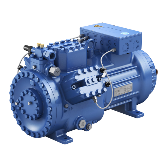
Oil pump Oil sight glass Fig. 1 Discharge shut-off valve (accessories) Terminal box Cylinder cover Suction shut-off valve (accessories) Fig. 2 Dimension and connection values can be found in chapter 9 6 | AQ452526009526en-000401 © Danfoss | Climate Solutions | 2023.12... -
Page 7: Type Key
ML - Normal cooling and deep freezing at low and medium evaporation temperatures - For frequency regulation and extended limits of application SH - For high evaporating temperatures eg. heat pumps, different oil charge AQ452526009526en-000401| 7 © Danfoss | Climate Solutions | 2023.12... -
Page 8: Type Key Compressors With Lspm Motor (Line Start Permanent Magnet)
MLP - Normal cooling and deep freezing at low and medium evaporation temperatures SP - For frequency regulation and extended limits of application SHP - For high evaporating temperatures eg. heat pumps, different oil charge 8 | AQ452526009526en-000401 © Danfoss | Climate Solutions | 2023.12... -
Page 9: E 3 Areas Of Application
- A minimum running time of 3 min. steady-state condition (continuous operation) must be achieved. Avoid continuous operation in limit range. Max. permissible operating LP = Low pressure : 100/150 bar pressure (LP/HP) HP = High pressure AQ452526009526en-000401| 9 © Danfoss | Climate Solutions | 2023.12... -
Page 10: Compressor Assembly
Do not use in a corrosive, dusty, damp atmosphere or a com- bustible environment. Setup on an even surface or frame with sufficient load-bearing capacity. Single compressor preferably on vibration damper. Compound connection basically rigid. 10 | AQ452526009526en-000401 © Danfoss | Climate Solutions | 2023.12... -
Page 11: Connecting The Pipelines - Solder System
After assembly, it is necessary to check the collar. The gasket must not be damaged. At least 80 % of the cutting face has to be covered. After check-up, screw on and tighten again as described above. AQ452526009526en-000401| 11 © Danfoss | Climate Solutions | 2023.12... -
Page 12: Pipes
CAUTION Risk of injury. The compressor must be depressurized through connections A1 and B1 before commencing any work and prior to connecting to the refrigerant system. Fig. 7 Fig. 8 12 | AQ452526009526en-000401 © Danfoss | Climate Solutions | 2023.12... -
Page 13: Laying Suction And Pressure Lines
Before opening or closing the shut-off valve, release the valve spindle seal by approx. of a turn counter-clockwise. After activating the shut-off valve, re-tighten the adjustable valve spindle seal clockwise. Tighten Release Valve spindle seal Fig. 11 Fig. 10 AQ452526009526en-000401| 13 © Danfoss | Climate Solutions | 2023.12... -
Page 14: Operating Mode Of The Lockable Service Connections
For systems with long pipes and higher degree of contamination, a filter on the suction-side is recommended. The filter has to be be renewed depending on the degree of contamina- tion (reduced pressure loss). 14 | AQ452526009526en-000401 © Danfoss | Climate Solutions | 2023.12... -
Page 15: Electrical Connection
In the L1 L2 case of special volt- ages, the instruc- tions affixed to the terminal box apply. Only direct start is possible with LSPM Motor. L1 L2 L1 L2 AQ452526009526en-000401| 15 © Danfoss | Climate Solutions | 2023.12... - Page 16 Cold conductor (PTC sensor) motor winding Thermal protection thermostat (PTC sensor) Load circuit safety switches Control power circuit fuse High pressure safety monitor Safety chain (high/low pressure monitoring ) Release switch (thermostat/pressostat) 16 | AQ452526009526en-000401 © Danfoss | Climate Solutions | 2023.12...
- Page 17 L1.1 L2.1 L3.1 L1.2 P> Θ Θ Main switch Control voltage switch Compressor motor Compressor contactor INT69 G Electronic trigger unit INT69 G Oil sump heater AQ452526009526en-000401| 17 © Danfoss | Climate Solutions | 2023.12...
-
Page 18: Electronic Trigger Unit Int69 G
5.6 Function test of the trigger unit INT69 G Before commissioning, after troubleshooting or making changes to the control power circuit, check the functionality of the trigger unit. Perform this check using a continuity tester or gauge. 18 | AQ452526009526en-000401 © Danfoss | Climate Solutions | 2023.12... -
Page 19: Oil Sump Heater
For start-up and low speed operation, a voltage boost of 10-20V is recommended to slightly reduce the motor current and compensate for voltage drops through the compressor supply line (and filtering devices, if present). AQ452526009526en-000401| 19 © Danfoss | Climate Solutions | 2023.12... -
Page 20: Commissioning
(see name plate data)! Do not mix any refrigerant with the nitrogen as this could cause the ignition limit to shift into the critical range. 20 | AQ452526009526en-000401 © Danfoss | Climate Solutions | 2023.12... -
Page 21: Evacuation
5.2 bar. WARNING Never exceed the max. permissible pressures while charging. Precautions must be taken in time. AQ452526009526en-000401| 21 © Danfoss | Climate Solutions | 2023.12... -
Page 22: Start-Up
(con- nections A and B, see Chapter 9). 22 | AQ452526009526en-000401 © Danfoss | Climate Solutions | 2023.12... -
Page 23: Decompression Valves
EN 378-2 or appropriate safety standards. Failure to observe can result in risk of injury from CO streaming out of the two decompression valves! streaming Fig. 17 AQ452526009526en-000401| 23 © Danfoss | Climate Solutions | 2023.12... -
Page 24: Avoiding Slugging
CO is produced which blocks the outlet and could hinder the streaming out of CO . Otherwise, there is the danger that pressure can be built up again. 24 | AQ452526009526en-000401 © Danfoss | Climate Solutions | 2023.12... -
Page 25: Work To Be Carried Out
For this reason the suction side (LP) and the high pressure side (HP) of the compressor have to be secured by decompression valves. AQ452526009526en-000401| 25 © Danfoss | Climate Solutions | 2023.12... -
Page 26: Technical Data
220-240 V ∆ / 380-420 V Y - 3 - 50 Hz Voltage 265-290 V ∆ / 440-480 V Y - 3 - 60 Hz Displacement (1450 / 1740 rpm) No. of cylinders Type HGX24/ 26 | AQ452526009526en-000401 © Danfoss | Climate Solutions | 2023.12... - Page 27 8 | Technical data AQ452526009526en-000401| 27 © Danfoss | Climate Solutions | 2023.12...
- Page 28 220-240 V ∆ / 380-420 V Y - 3 - 50 Hz Voltage 265-290 V ∆ / 440-480 V Y - 3 - 60 Hz Displacement (1500 / 1800 rpm) No. of cylinders Type HGX24/ 28 | AQ452526009526en-000401 © Danfoss | Climate Solutions | 2023.12...
- Page 29 8 | Technical data AQ452526009526en-000401| 29 © Danfoss | Climate Solutions | 2023.12...
-
Page 30: Dimensions And Connections
08.06.21 C. Polizzi C. Egeler 30 | AQ452526009526en-000401 © Danfoss | Climate Solutions | 2023.12 e reproduction, distribution and utilization of this uss sicherstellen, dass die Ware Der Lieferant muss sicherstellen, dass die Ware cument as well as the communication of its... - Page 31 Connection oil temperature sensor Decompression valve HP M24x1,5 Decompression valve LP M22x1,5 7 / 16 “ UNF Connection for Schrader valve, suction side 7 / 16 “ UNF Connection for Schrader valve, discharge side AQ452526009526en-000401| 31 © Danfoss | Climate Solutions | 2023.12...
-
Page 32: Declaration Of Incorporation
Bock GmbH Authorized person for compiling and handing Alexander Layh over technical documentation: Benzstraße 7 72636 Frickenhausen, Germany Frickenhausen, 04th of January 2021 i. A. Alexander Layh, Global Head of R&D 32 | AQ452526009526en-000401 © Danfoss | Climate Solutions | 2023.12... - Page 33 Bock GmbH Authorized person for compiling and handing Alexander Layh over technical documentation: Benzstraße 7 72636 Frickenhausen, Germany Frickenhausen, 14th of October 2022 i. A. Alexander Layh, Global Head of R&D AQ452526009526en-000401| 33 © Danfoss | Climate Solutions | 2023.12...
- Page 34 34 | AQ452526009526en-000401 © Danfoss | Climate Solutions | 2023.12...
Need help?
Do you have a question about the BOCK HGX24 CO2 T and is the answer not in the manual?
Questions and answers