Table of Contents
Advertisement
Quick Links
FK 4
®
BOCK
Operating guide
FK40/390 N
FK40/390 K
FK40/470 N
FK40/470 K
FK40/560 N
FK40/560 K
FK40/655 N
FK40/655 K
FK40/755 K
FKX40/390 N
FKX40/390 K
FKX40/470 N
FKX40/470 K
FKX40/560 N
FKX40/560 K
FKX40/655 N
FKX40/655 K
FKX40/755 K
Translation of the original instructions
0
FK40/390 K1
FK40/470 K1
FK40/560 K1
FK40/655 K1
FK40/755 K1
FKX40/390 K1
FKX40/470 K1
FKX40/560 K1
FKX40/655 K1
FKX40/755 K1
FK40/390 TK
FK40/470 TK
FK40/560 TK
FK40/655 TK
FKX40/390 TK
FKX40/470 TK
FKX40/560 TK
FKX40/655 TK
AQ453249013813en-000201
Advertisement
Table of Contents

Subscribe to Our Youtube Channel
Related Manuals for Danfoss BOCK FK40


Summary of Contents for Danfoss BOCK FK40
- Page 1 FK 4 ® BOCK Operating guide FK40/390 N FK40/390 K FK40/390 K1 FK40/390 TK FK40/470 N FK40/470 K FK40/470 K1 FK40/470 TK FK40/560 N FK40/560 K FK40/560 K1 FK40/560 TK FK40/655 N FK40/655 K FK40/655 K1 FK40/655 TK FK40/755 K FK40/755 K1 FKX40/390 N FKX40/390 K...
- Page 2 Such persons must read the safety advice and have understood it. Bock assumes no liability for any damage arising from non-compliance. 2 | AQ453249013813en-000201 © Danfoss | Climate Solutions | 2023.07...
-
Page 3: Table Of Contents
6.4 Recommended spare parts/accessories 6.5 Integrated decompression valve 6.6 Lubricants / Oils 6.7 Decommissioning Accessories 7.1 Capacity regulator 7.2 Thermal protection thermostat Technical data Dimensions and connections 10 Declaration of incorporation AQ453249013813en-000201| 3 © Danfoss | Climate Solutions | 2023.07... -
Page 4: Safety
• If there is a sharp reduction in refrigerating capacity, switch the compressor off immediately. • Secure the compressor against being switched on again. • In such cases do not continue to operate the compressor under any circumstances. 4 | AQ453249013813en-000201 © Danfoss | Climate Solutions | 2023.07... -
Page 5: Safety Instructions
Commissioning is permissible only if the compressor has been installed in accordance with these as- sembly instructions and the entire system into which it is integrated has been inspected and approved in accordance with legal regulations. AQ453249013813en-000201| 5 © Danfoss | Climate Solutions | 2023.07... -
Page 6: Product Description
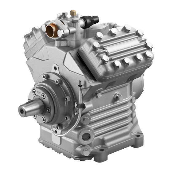
Shaft end Oil sight glass Fig. 1 Cylinder cover Suction shut-off valve Valve plate Oil pump Oil sight glass Fig. 2 Dimension and connection values can be found in Chapter 9 6 | AQ453249013813en-000201 © Danfoss | Climate Solutions | 2023.07... -
Page 7: Type Key
Swept volume Size Ester oil charge ² Series ¹ K - specially for air-conditioning N - specially for air-conditioning or normal cooling TK - specially for deep freezing X - Ester oil charge (HFC refrigerant, e.g. R134a, R407C) ² AQ453249013813en-000201| 7 © Danfoss | Climate Solutions | 2023.07... -
Page 8: Areas Of Application
Prevent the ingress of air at all costs! Maximum admissible LP = Low pressure operating pressure (g) HP = High pressure (LP/HP) : 19/28 bar 8 | AQ453249013813en-000201 © Danfoss | Climate Solutions | 2023.07... -
Page 9: Compressor Assembly
4.2 Maximum permissible inclination ATTENTION Poor lubrication can damage the compressor. Respect the stated values. max. 30°, max. 2 minutes max. 15°, continuous operation Fig. 6 AQ453249013813en-000201| 9 © Danfoss | Climate Solutions | 2023.07... -
Page 10: V-Belt Drive
The following description applies for an electromagnetic clutch secured to a shaft. To absorb the magnetic field of the electromagnetic clutch, the front bearing flange has a snug fit Ø 148 h8 (see Fig. 8). To connect the magnetic field, loosen the 4 cheese head screws M8 on the bearing flange (see Fig. 8). Slide the magnetic field to a snug fit and re-attach using the four cheese head screws M8 (Fig. 9). Screw torque = 37 Nm. Further assembly of the electromagnetic clutch according to the clutch manufacturer. Bearing flange, front Magnetic field Fig. 8 Fig. 9 148 h8 10 | AQ453249013813en-000201 © Danfoss | Climate Solutions | 2023.07... -
Page 11: Pipe Connections
Before opening or closing the shut-off valve, release the valve spindle seal by approx. ¼ of a turn counter-clockwise. After activating the shut-off valve, re-tighten the adjustable valve spindle seal clockwise. Release Tighten Valve spindle seal Fig. 11 Fig. 12 AQ453249013813en-000201| 11 © Danfoss | Climate Solutions | 2023.07... -
Page 12: Operating Mode Of The Lockable Service Connections
Connection 3 is provided for safety devices and is not lockable. After activating the spindle, generally fit the spindle protection cap again and tighten with 14-16 Nm. This serves as a second sealing feature during operation. 4.10 Suction pipe filter For systems with long pipes and higher degree of contamination, a filter on the suction-side is recommended. The filter has to be be renewed depending on the degree of contamination (reduced pressure loss). 12 | AQ453249013813en-000201 © Danfoss | Climate Solutions | 2023.07... -
Page 13: Characteristics For K1 Special Housing
It must be ensured that the compressor housing is not Oberflä Unbemaßte Radien / Undimensioned radii: Indicatio distorted during installation. The specifications of the motor / chassis DIN EN manufacturer are mandatory. AQ453249013813en-000201| 13 © Danfoss | Climate Solutions | 2023.07... -
Page 14: Preparations For Start-Up Pt
Evacuate the suction and discharge pressure sides using the vacuum pump. At the end of the evacuation process, the vacuum should be < 1.5 mbar when the pump is switched off. Repeat the process as often as is required. 14 | AQ453249013813en-000201 © Danfoss | Climate Solutions | 2023.07... -
Page 15: Refrigerant Charge Tr
0.05 ml per operating hour is therefore normal. This applies particularly during the run-in phase (200 - 300 h). T o trap and collect leaked oil, the FK40 is fitted with an inte- grated leak oil trapping device with oil reservoir (P.6, Fig. 1). AQ453249013813en-000201| 15 © Danfoss | Climate Solutions | 2023.07... -
Page 16: Avoiding Liquid Shocks
• An oil change is also necessary, if the oil is very cloudy and dark, or after repairs have been carried out on the compressor. Emptying the shaft seal oil reservoir: As required depending on use, but at the latest after 1 year or approx. 1,400 operating hours 16 | AQ453249013813en-000201 © Danfoss | Climate Solutions | 2023.07... -
Page 17: Shaft Seal, Emptying The Oil Reservoir
• Thermal overload (operation outside the limits of application) • Frequent cycling • Long periods of stoppage • Material deposits / dirt from the system Due to these effects, the shaft seal can develop leaks, and it must then be replaced. AQ453249013813en-000201| 17 © Danfoss | Climate Solutions | 2023.07... -
Page 18: Recommended Spare Parts/Accessories
Remove the compressor using an appropri- ate hoist. Dispose of the oil inside in accordance with the valid national regulations. 18 | AQ453249013813en-000201 © Danfoss | Climate Solutions | 2023.07... -
Page 19: Accessories
Ref. No.* Ref. No.* Special accessory 12 V 097B08703 097B08708 Special accessory 24 V 097B08704 097B08709 For a description, see technical information "Capacity regulation" (Item No. 09900) If the capacity regulator is factory-fitted, it is integrated into an extra, dedicated cylinder cover. For retrofits, it is supplied with the cylinder cover. The regulator closes one cylinder bank (capacity regula- tion approx. 50%). * Please note that the legacy BOCK ref. numbers are without 097B AQ453249013813en-000201| 19 © Danfoss | Climate Solutions | 2023.07... -
Page 20: Thermal Protection Thermostat
2.5 A at 24 V DC Switch-off temperature : 145 °C ± 5 K Switch-on temperature : approx. 115 °C * Please note that the legacy BOCK ref. numbers are without 097B 20 | AQ453249013813en-000201 © Danfoss | Climate Solutions | 2023.07... -
Page 21: Technical Data
8| Technical data No. of cylinders AQ453249013813en-000201| 21 © Danfoss | Climate Solutions | 2023.07... -
Page 22: Dimensions And Connections
C - FK40/655 N ±0.1 ±0.2 ±0.3 ±0.5 ±0.8 22 | AQ453249013813en-000201 © Danfoss | Climate Solutions | 2023.07 Oberflächenbehandlung, Härte / Treatment of surface, Ha Oberflächenangaben / Unbemaßte Radien / Undimensioned radii: Indication of surface texture DIN EN ISO 1302... - Page 23 2 x 1 1 / 8 "- 18 UNEF Sight glass Connection thermal protection thermostat 8 " NPTF Oil filter M22 x 1.5 Opt. connection for suction line valve = No connection available as standard. Available on request (Connection M22 x 1,5) AQ453249013813en-000201| 23 © Danfoss | Climate Solutions | 2023.07...
-
Page 24: Declaration Of Incorporation
Bock GmbH Authorized person for compiling and handing Alexander Layh over technical documentation: Benzstraße 7 72636 Frickenhausen, Germany Frickenhausen, 04th of January 2021 i. A. Alexander Layh, Global Head of R&D 24 | AQ453249013813en-000201 © Danfoss | Climate Solutions | 2023.07... - Page 25 Bock GmbH Authorized person for compiling and handing Alexander Layh over technical documentation: Benzstraße 7 72636 Frickenhausen, Germany Frickenhausen, 14th of October 2022 i. A. Alexander Layh, Global Head of R&D AQ453249013813en-000201| 25 © Danfoss | Climate Solutions | 2023.07...
- Page 26 26 | AQ453249013813en-000201 © Danfoss | Climate Solutions | 2023.07...
Need help?
Do you have a question about the BOCK FK40 and is the answer not in the manual?
Questions and answers