Table of Contents
Advertisement
Quick Links
®
BOCK
HG66e
Operating guide
HG66e/1340-4
HG66e/1540-4
HG66e/1750-4
HG66e/2070-4
HGX66e/1340-4
HGX66e/1540-4
HGX66e/1750-4
HGX66e/2070-4
Translation of the original instructions
HG66e/1340-4 S
HG66e/1540-4 S
HG66e/1750-4 S
HG66e/2070-4 S
HGX66e/1340-4 S
HGX66e/1540-4 S
HGX66e/1750-4 S
HGX66e/2070-4 S
AQ450740142615en-000201
Advertisement
Table of Contents

Related Manuals for Danfoss BOCK HG66e


Summary of Contents for Danfoss BOCK HG66e
- Page 1 ® BOCK HG66e Operating guide HG66e/1340-4 HG66e/1340-4 S HG66e/1540-4 HG66e/1540-4 S HG66e/1750-4 HG66e/1750-4 S HG66e/2070-4 HG66e/2070-4 S HGX66e/1340-4 HGX66e/1340-4 S HGX66e/1540-4 HGX66e/1540-4 S HGX66e/1750-4 HGX66e/1750-4 S HGX66e/2070-4 HGX66e/2070-4 S Translation of the original instructions AQ450740142615en-000201...
- Page 2 Observe the safety instructions contained in these instructions. These instructions must be passed onto the end customer along with the unit in which the compres- sor is installed. © Danfoss | Climate Solutions | 2023.07 2 | AQ450740142615en-000201...
-
Page 3: Table Of Contents
7.3 Spare parts recommendation / accessories 7.4 Lubricants / oil 7.5 Decommissioning Accessories 8.1 Capacity regulator 8.2 Oil separator 8.3 Oil level regulator Technical data Dimensions and connections Declaration of incorporation © Danfoss | Climate Solutions | 2023.07 AQ450740142615en-000201 | 3... -
Page 4: Safety
As well as professions with comparable training, which enables personnel to assemble, install, maintain and repair refrigeration and air-conditioning systems. Personnel must be capable of assessing the work to be carried out and recognising any potential dangers. © Danfoss | Climate Solutions | 2023.07 4 | AQ450740142615en-000201... -
Page 5: General Safety Instructions
The compressors are intended for use in refrigeration systems in compliance with the limits of application. Only the refrigerant specified in these instructions may be used. Any other use of the compressor is prohibited! © Danfoss | Climate Solutions | 2023.07 AQ450740142615en-000201 | 5... -
Page 6: Product Description
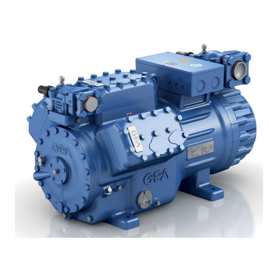
Discharge shut-off valve Cylinder Valve plate cover Name plate Motor section Oil pump Drive section Oil sight glass Fig. 1 Dimension and connection values can be found in Chapter 10 © Danfoss | Climate Solutions | 2023.07 6 | AQ450740142615en-000201... -
Page 7: Type Key
HG - Hermetic Gas-Cooled (suction gas-cooled) for the normal- / air conditioning applications ² X - Ester oil charge (HFC refrigerant, e.g. R134a, R404A/R507, R407C, R407F) S - More powerful motor, e.g. for air-conditioning applications © Danfoss | Climate Solutions | 2023.07 AQ450740142615en-000201 | 7... -
Page 8: Areas Of Application
When operating in the vacuum range, there is a danger of air entering on the suction side. This can cause chemical reactions, a pressure rise in the condenser and an elevated compressed-gas temperature. Prevent the ingress of air at all costs! © Danfoss | Climate Solutions | 2023.07 8 | AQ450740142615en-000201... - Page 9 3 | Areas of application Maximum admissible Maximum admissible operating frequency: 60 Hz pressure (LP/HP) : 19/28 bar LP = Low pressure HP = High pressure © Danfoss | Climate Solutions | 2023.07 AQ450740142615en-000201 | 9...
-
Page 10: Compressor Assembly
Ensure adequate compressor ventilation. Do not use in a corrosive, dusty, damp atmosphere or a combustible environment. Setup on an even surface or frame with sufficient load-bearing capacity. Single compressor preferably on vibration damper. Duplex and parallel circuits always rigid. Installation of pipe vibration mufflers is recommended! © Danfoss | Climate Solutions | 2023.07 10 | AQ450740142615en-000201... -
Page 11: Pipe Connections
As soon as the motor and the compressor reach their rated speed, the solenoid valve closes and the non-return valve opens (Fig. 6). The compressor now works under normal load. Solenoid valve actuated Non-return valve closed Fig. 5 © Danfoss | Climate Solutions | 2023.07 AQ450740142615en-000201 | 11... -
Page 12: Laying Suction And Pressure Lines
A rule of thumb: Always lay the first pipe section starting from the shut-off valve downwards and parallel to the drive shaft. Rigid As short as fixed point Fig. 7 possible © Danfoss | Climate Solutions | 2023.07 12 | AQ450740142615en-000201... -
Page 13: Operating The Shut-Off Valves
Opening the service connection Spindle: Turn 1 / 2 - 1 turn clockwise. —> Service connection opened / shut-off valve opened. After activating the spindle, generally fit the spindle protection cap again and tighten with 14-16 Nm. This serves as a second sealing feature during operation. © Danfoss | Climate Solutions | 2023.07 AQ450740142615en-000201 | 13... -
Page 14: Suction Pipe Filter And Filter Drier
For motor protection use a current-dependent and time-delayed overload protection device for moni- toring all three phases. Set the overload protection device so that it must be actuated within 2 hours, if there is 1.2 times the max. working current. © Danfoss | Climate Solutions | 2023.07 14 | AQ450740142615en-000201... -
Page 15: Standard Motor, Design For Direct Or Partial Winding Start
After the motor starts up via partial winding 1, partial winding 2 must be switched on after a maximum delay of one second. Failure to comply can adversely affect the service life of the motor. © Danfoss | Climate Solutions | 2023.07 AQ450740142615en-000201 | 15... - Page 16 Release switch (thermostat) Datum 20.02.2009 Bearb. bauknecht DELTA-P II Oil differential pressure sensor DELTA-P II (accessory) Gepr. 03.11.2020 Oil sump heater Οnderung Datum Name Norm Urspr. Ers. f. Ers. d. Compressor motor © Danfoss | Climate Solutions | 2023.07 16 | AQ450740142615en-000201...
- Page 17 Electronic trigger unit INT69 G Delay relay for contactor switch over Main switch PW INT69 HG44/66 Mains contactor (part winding 1) Mains contactor (part winding 2) BOCK COMPRESSORS Control voltage switch © Danfoss | Climate Solutions | 2023.07 AQ450740142615en-000201 | 17...
-
Page 18: Special Motor: Design For Direct Or Star-Delta Start
Sticker on the terminal box ∆ / Y ∆ / Y Stern-Dreieck-Anlauf ist nur im Spannungsbereich ∆ (230 V) möglich. Beispiel: 230 V ∆ 400 V Y Direktstart Stern-Dreieck-Start nur Direktstart © Danfoss | Climate Solutions | 2023.07 18 | AQ450740142615en-000201... - Page 19 Direktstart Stern-Dreieck-Start nur Direktstart In the factory the motor is wired for direct starting at high voltage. The brides are to be removed for star delta starting at low voltage. © Danfoss | Climate Solutions | 2023.07 AQ450740142615en-000201 | 19...
-
Page 20: Basic Circuit Diagram For Star-Delta Start 230 V ∆ / 400 V Y
Release switch (thermostat) Datum 20.02.2009 DELTA-P II Oil differential pressure sensor DELTA-P II (accessory) Bearb. bauknecht Oil sump heater Gepr. 03.11.2020 Οnderung Datum Name Norm Urspr. Ers. f. Ers. d. Compressor motor © Danfoss | Climate Solutions | 2023.07 20 | AQ450740142615en-000201... - Page 21 Electronic trigger unit INT69 G Delay relay for contactor switch over Main switch D/S INT69 HG44/66 neu Mains contactor (part winding 1) Mains contactor (part winding 2) BOCK COMPRESSORS Control voltage switch © Danfoss | Climate Solutions | 2023.07 AQ450740142615en-000201 | 21...
-
Page 22: Electronic Trigger Unit Int69 G
This would destroy the trigger N 43 43 11 X2 1 unit INT69 G and PTC sensors. Θ Θ Θ Steuerstrom- Steuerstrom- Control circuit kreis kreis Θ Fig. 14 Terminal box © Danfoss | Climate Solutions | 2023.07 22 | AQ450740142615en-000201... -
Page 23: Oil Sump Heater
El. data: 230 V - 1 - 50/60 Hz, 160 W. Plan de raccordement pour résistance de carter d‘huile Fig. 16 ATTENTION Connection to the current path of the safety control chain is not permitted. © Danfoss | Climate Solutions | 2023.07 AQ450740142615en-000201 | 23... -
Page 24: Selection And Operation Of Compressors With Frequency Converters
4. Carry out all designs and installations in accordance with the local safety regulations and common rules (e.g. VDE) and regulations as well as in accordance with the specifications of the frequency converter manufacturer The permissible frequency range can be found in the technical data. Rotational speed 0 - f-min f-min - f-max range Start-up time < 1 s ca. 4 s immediately Switch-off time f-min/f-max see chapter: Technical data: adjustable frequency range © Danfoss | Climate Solutions | 2023.07 24 | AQ450740142615en-000201... -
Page 25: Commissioning
Evacuate the suction and discharge pressure sides using the vacuum pump. At the end of the evacuation process, the vacuum should be < 1.5 mbar when the pump is switched off. Repeat this process as often as is required. © Danfoss | Climate Solutions | 2023.07 AQ450740142615en-000201 | 25... -
Page 26: Refrigerant Charge
The system must reach a state of equilibrium. Particularly in critical systems (e.g. several evaporator points), measures are recommended such as replacement of liquid traps, solenoid valve in the liquid line, etc. There should be no movement of coolant whatsoever while the compressor is at a standstill. © Danfoss | Climate Solutions | 2023.07 26 | AQ450740142615en-000201... -
Page 27: Maintenance
When the compressor is depressurised, undo the fastening screws of the shut-off valves. Remove the compressor using an appropriate hoist. Dispose of the oil inside in accordance with the applicable national regulations. © Danfoss | Climate Solutions | 2023.07 AQ450740142615en-000201 | 27... -
Page 28: Accessories
15 Nm. Magnetic coil Wet thread sides with ester oil. Control unit Insert magnetic coil, fasten it with knurled (pilot valve) nut and connect it. Seal ring Fig. 21 © Danfoss | Climate Solutions | 2023.07 28 | AQ450740142615en-000201... -
Page 29: Oil Separator
The oil return from the oil separator must be guided back at the intended connection (D1) on the compressor housing. A direct oil return into the suction line from the oil separator is not permissible. Ensure that the oil separator is properly dimensioned. © Danfoss | Climate Solutions | 2023.07 AQ450740142615en-000201 | 29... -
Page 30: Oil Level Regulator
3-Loch-Anschlussbild für ESK, Mechanical oil level regulator 3 hole connection diagram for AC&R und CARLY ESK, AC&R and CARLY at the "O" connection 3-Loch-Anschlussbild für TraxOil 3 hole diagram for TraxOil © Danfoss | Climate Solutions | 2023.07 30 | AQ450740142615en-000201... -
Page 31: Technical Data
440-480 V Y/YY - 3 - 60 Hz PW Voltage PW = Part Winding Winding ratio : 50 % / 50 % Displacement (1450 / 1740 rpm) No. of cylinders Type HG66e/ © Danfoss | Climate Solutions | 2023.07 AQ450740142615en-000201 | 31... -
Page 32: Dimensions And Connections
Rechte für den Fall der Patent-, Gebrauchsmuster- Massenschwerpunkt Änderungen vorbehalten Maße in mm oder Geschmacksmustereintragung vorbehalten. 0c | Betrifft Blatt 3 © Danfoss | Climate Solutions | 2023.07 11132 08.03.21 S. Büttner A. Layh 32 | AQ450740142615en-000201 Centre of gravity Subject to change without notice... - Page 33 3 x M6 Oil pressure differential sensor M20x1,5 ÖV Connection oil service valve 1/4" NPTF Connection oil temperature sensor 1/8" NPTF 1 / 8 Connection for refrigerant injection “ NPTF © Danfoss | Climate Solutions | 2023.07 AQ450740142615en-000201 | 33...
- Page 34 Prasad Sannagowder #3A1, Bommasandra Industrial Area, Hebbagodi, Bock GmbH Hosur Road, Bangalore – 560099 Alexander Layh Benzstraße 7 72636 Frickenhausen, Germany Prasad Sannagowder, Managing Director Frickenhausen, 02nd of March 2021 © Danfoss | Climate Solutions | 2023.07 34 | AQ450740142615en-000201...
-
Page 35: Declaration Of Incorporation
Prasad Sannagowder #3A1, Bommasandra Industrial Area, Hebbagodi, Bock GmbH Hosur Road, Bangalore – 560099 Alexander Layh Benzstraße 7 72636 Frickenhausen, Germany Prasad Sannagowder, Managing Director Frickenhausen, 14th of October 2022 © Danfoss | Climate Solutions | 2023.07 AQ450740142615en-000201 | 35... - Page 36 © Danfoss | Climate Solutions | 2023.07 36 | AQ450740142615en-000201...
Need help?
Do you have a question about the BOCK HG66e and is the answer not in the manual?
Questions and answers