Table of Contents
Advertisement
Quick Links
Advertisement
Table of Contents

Related Manuals for Danfoss BOCK HG7


Summary of Contents for Danfoss BOCK HG7
- Page 1 HG 7 ® BOCK Operating guide HG7/1620-4 HG7/1620-4 S HGX7/1620-4 HGX7/1620-4 S HG7/1860-4 HG7/1860-4 S HGX7/1860-4 HGX7/1860-4 S HG7/2110-4 HG7/2110-4 S HGX7/2110-4 HGX7/2110-4 S Translation of the original instructions AQ451328892160en-000201...
- Page 2 Observe the safety instructions contained in these instructions. These instructions must be passed onto the end customer along with the unit in which the compres- sor is installed. 2 | AQ451328892160en-000201 © Danfoss | Climate Solutions | 2023.07...
-
Page 3: Table Of Contents
6.8 Connection of oil level regulator Maintenance 7.1 Preparation 7.2 Work to be carried out 7.3 Spare parts recommendation/accessories 7.4 Lubricants / oil 7.5 Decommissioning Technical data Dimensions and connections Declaration of installation AQ451328892160en-000201 | 3 © Danfoss | Climate Solutions | 2023.07... -
Page 4: Safety
As well as professions with comparable training, which enables personnel to assemble, install, maintain and repair refrigeration and air-conditioning systems. Personnel must be capable of assessing the work to be carried out and recognising any potential dangers. 4 | AQ451328892160en-000201 © Danfoss | Climate Solutions | 2023.07... -
Page 5: General Safety Instructions
The compressors are intended for use in refrigeration systems in compliance with the limits of application. Only the refrigerant specified in these instructions may be used. Any other use of the compressor is prohibited! AQ451328892160en-000201 | 5 © Danfoss | Climate Solutions | 2023.07... -
Page 6: Product Description
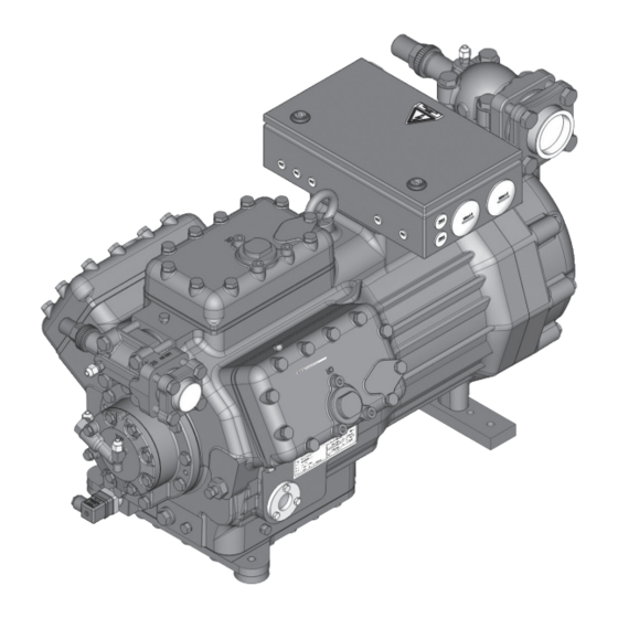
Cylinder Valve plate cover Discharge Motor section shut-off valve Name plate Oil pump Drive section Oil sight glass Fig. 1 Dimension and connection values can be found in Chapter 9 6 | AQ451328892160en-000201 © Danfoss | Climate Solutions | 2023.07... -
Page 7: Type Key
HG - Hermetic-Gas-cooled (suction gas cooled) for the normal- / air conditioning applications X - Ester oil filling (HFC refrigerant, e.g. R134a, R404A, R507, R407C) S - Stronger motor e.g. air conditioning applications AQ451328892160en-000201 | 7 © Danfoss | Climate Solutions | 2023.07... -
Page 8: Areas Of Application
When operating in the vacuum range, there is a danger of air entering on the suction side. This can cause chemical reactions, a pressure rise in the condenser and an elevated compressed-gas temperature. Prevent the ingress of air at all costs! 8 | AQ451328892160en-000201 © Danfoss | Climate Solutions | 2023.07... - Page 9 (HP): 28 bar Design for other areas on request Fig. 6 HG7 „Motor version S“ in the evaporation range of = 5°C to 12,5°C limited condensing temperature up to t = 50°C. Fig. 7 AQ451328892160en-000201 | 9 © Danfoss | Climate Solutions | 2023.07...
-
Page 10: Compressor Assembly
4.3 Pipe connections ATTENTION Damage possible. Superheating can damage the valve. Remove the pipe supports from the valve for soldering. Only solder using inert gas to inhibit oxidation products (scale). 10 | AQ451328892160en-000201 © Danfoss | Climate Solutions | 2023.07... -
Page 11: Pipes
A rule of thumb: Always lay the first pipe section starting from the shut-off valve downwards and parallel to the drive shaft. Rigid fixed point As short as possible Fig. 14 AQ451328892160en-000201 | 11 © Danfoss | Climate Solutions | 2023.07... -
Page 12: Operating The Shut-Off Valves
—> Service connection opened / shut-off valve opened. The connection which cannot be shut off is intended for safety devices. After activating the spindle, generally fit the spindle protection cap again and tighten with 14-16 Nm. This serves as a second sealing feature during operation. 12 | AQ451328892160en-000201 © Danfoss | Climate Solutions | 2023.07... -
Page 13: Suction Pipe Filter
For motor protection use a current-dependent and time-delayed overload protection device for moni- toring all three phases. Set the overload protection device so that it must be actuated within 2 hours, if there is 1.2 times the max. working current. AQ451328892160en-000201 | 13 © Danfoss | Climate Solutions | 2023.07... -
Page 14: Basic Circuit Diagram For Part Winding Start With Standard Motor
High pressure safety monitor Safety chain (high/low pressure monitoring) Oil differential pressure monitor Release switch (thermostat) Datum 20.Feb.2009 Bearb. Kelich Gepr. 03.Nov.2010 Žnderung Datum Name Norm Urspr. Ers. f. Ers. d. 14 | AQ451328892160en-000201 © Danfoss | Climate Solutions | 2023.07... - Page 15 P< P™l Main switch Compressor motor Mains contactor (part winding 1) Mains contactor (part winding 2) Delay relay max. 1s Control voltage switch Oil sump heater PW MP10 BOCK COMPRESSORS AQ451328892160en-000201 | 15 © Danfoss | Climate Solutions | 2023.07...
-
Page 16: Standard Motor, Design For Direct Or Partial Winding Start
After the motor starts up via partial winding 1, partial winding 2 must be switched on after a maximum delay of one second . Failure to comply can adversely affect the service life of the motor. 16 | AQ451328892160en-000201 © Danfoss | Climate Solutions | 2023.07... -
Page 17: Special Motor: Design For Direct Or Star-Delta Start
∆ ∆ ∆ Star-delta start-up is only possible for 230 V power supply. Example: 230 V ∆ ∆ ∆ ∆ 400 V Y Direct start Star-delta start only direct start AQ451328892160en-000201 | 17 © Danfoss | Climate Solutions | 2023.07... - Page 18 High pressure safety monitor Safety chain (high/low pressure monitoring) Oil differential pressure monitor Release switch (thermostat) Datum 20.Feb.2009 Bearb. Kelich Gepr. 03.Nov.2010 Žnderung Datum Name Norm Urspr. Ers. f. Ers. d. 18 | AQ451328892160en-000201 © Danfoss | Climate Solutions | 2023.07...
- Page 19 L1.1 L2.1 L3.1 L1.2 P> P< P™l Main switch Compressor motor Mains contactor ∆-contactor Y-contactor Delay relay for contactor changeover Control voltage switch Oil sump heater PW MP10 BOCK COMPRESSORS AQ451328892160en-000201 | 19 © Danfoss | Climate Solutions | 2023.07...
-
Page 20: Electronic Trigger Unit Mp
PTC sensors. The supply voltage at L1-N (+/- for DC 24 V version) must be identical to the voltage at terminals 11, 12, 14 and 43. Fig. 21 Terminal box 20 | AQ451328892160en-000201 © Danfoss | Climate Solutions | 2023.07... - Page 21 • Reconnect terminals 1 or 2 and/or 3 or 4 Restore the power supply (L1 or S1): • MP 10 is operational again • The compressor and the trigger unit MP10 are operational when the H3 LED (green) lights. AQ451328892160en-000201 | 21 © Danfoss | Climate Solutions | 2023.07...
-
Page 22: Oil Sump Heater (Accessories)
El. data: 230 V - 1 - 50/60 Hz, 140 W. Fig. 22 ATTENTION The oil sump heater must not be connected to the electrical circuit of the safety control chain. 22 | AQ451328892160en-000201 © Danfoss | Climate Solutions | 2023.07... -
Page 23: Commissioning
Evacuate the suction and discharge pressure sides using the vacuum pump. At the end of the evacuation process, the vacuum should be < 1.5 mbar when the pump is switched off. Repeat this process as often as is required. AQ451328892160en-000201 | 23 © Danfoss | Climate Solutions | 2023.07... -
Page 24: Refrigerant Charge
Switch on the compressor and allow to run for a minimum of 10 min. Check the oil level by: The oil must be visible in the sightglass. ATTENTION I f larger quantities of oil have to be topped up, there is a risk of oil hammer effects. If this is the case check the oil return! 24 | AQ451328892160en-000201 © Danfoss | Climate Solutions | 2023.07... -
Page 25: Avoiding Slugging
3 hole connection diagramm for 3-Loch-Anschlussbild für ESK, Mechanical oil level regulator ESK, AC&R and CARLY AC&R und CARLY at the "O" connection 3-Loch-Anschlussbild für TraxOil 3 hole diagramm for TraxOil AQ451328892160en-000201 | 25 © Danfoss | Climate Solutions | 2023.07... -
Page 26: Maintenance
7.3 Spare part recommendation/accessories Available spare parts and accessories can be found on our compressor selection tool under vap.bock.de as well as at bockshop.bock.de. Only use genuine Bock spare parts! 26 | AQ451328892160en-000201 © Danfoss | Climate Solutions | 2023.07... -
Page 27: Lubricants / Oil
When the compressor is depressurised, undo the fastening screws of the shut-off valves. Remove the compressor using an appropriate hoist. Dispose of the oil inside in accordance with the applicable national regulations. AQ451328892160en-000201 | 27 © Danfoss | Climate Solutions | 2023.07... -
Page 28: Technical Data
380-420 V Y/YY - 3 - 50 Hz PW 440-480 V Y/YY - 3 - 60 Hz PW PW = Part Winding Winding ratio : 50% / 50% No. of cylinders 28 | AQ451328892160en-000201 © Danfoss | Climate Solutions | 2023.07... -
Page 29: Dimensions And Connections
9| Dimensions and connections Centre of gravity ca.315 ca.830 ca.510 ÖV Vibration damper Dimensions in mm Fig. 24 AQ451328892160en-000201 | 29 © Danfoss | Climate Solutions | 2023.07 ... - Page 30 Connection oil level regulator 3 x M6 Connection oil service valve 4 “ NPTF ÖV Connection oil differential pressure sensor M22 x 1,5 Connection oil temperature sensor 8 “ NPTF 30 | AQ451328892160en-000201 © Danfoss | Climate Solutions | 2023.07...
-
Page 31: Declaration Of Installation
Bock GmbH Authorized person for compiling and handing Alexander Layh over technical documentation: Benzstraße 7 72636 Frickenhausen, Germany Frickenhausen, 04th of January 2021 i. A. Alexander Layh, Global Head of R&D AQ451328892160en-000201 | 31 © Danfoss | Climate Solutions | 2023.07... - Page 32 32 | AQ451328892160en-000201 © Danfoss | Climate Solutions | 2023.07...
- Page 33 AQ451328892160en-000201 | 33 © Danfoss | Climate Solutions | 2023.07...
- Page 34 34 | AQ451328892160en-000201 © Danfoss | Climate Solutions | 2023.07...
Need help?
Do you have a question about the BOCK HG7 and is the answer not in the manual?
Questions and answers