Advertisement
www.ti.com
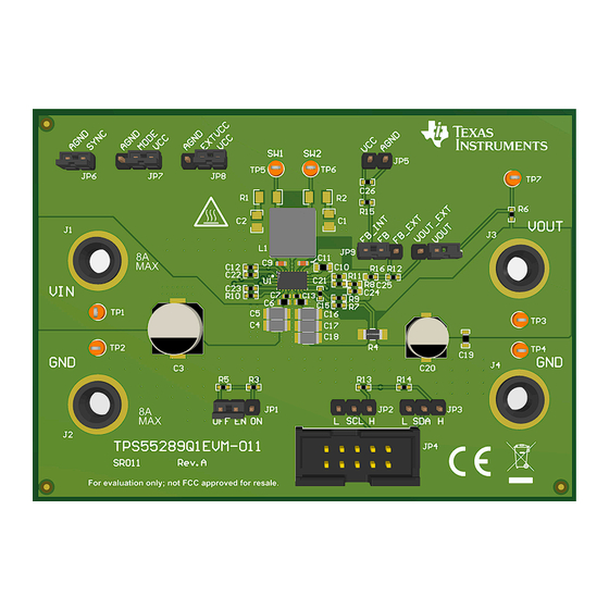
EVM User's Guide: TPS55289Q1EVM-011
TPS55289-Q1 Buck-Boost Converter Evaluation Module
Description
The TPS55289-Q1 integrates four MOSFETs
providing a compact design for a variety of
applications and is optimized for converting battery
voltage into power supply rails. Through the I
interface, the output voltage can be programmed
from 0.8V to 22 V with 10 mV step and the output
current limit is programmable up to 6.35A with 50
mA step, which is a good choice for USB Power
Delivery (USB PD) applications. The TPS55289-
Q1 has adjustable external loop compensation,
programmable switching frequency, optional spread
spectrum and rich protection features. All these
features bring flexibility and design optimization for
overall performance, as well as BOM optimization and
design cost.
Get Started
1. Order the EVM at ti.com.
2. Read the user's guide carefully.
3. Prepare the bench setup per instructions. Take
precautions to prevent damage by ESD when
handling the EVM.
4. Power up the EVM by following the recommended
steps.
5. Run tests and measurements. Take cautions of
high voltage and hot temperature produced by the
EVM during test.
SLVUCU2 – DECEMBER 2023
Submit Document Feedback
Features
•
Wide input and output voltage range
•
Programmable power supply (PPS) support
2
•
I
C interface
2
C
•
Programmable output voltage from 0.8V to 22 V
with 10 mV step
•
Programmable output current limit up to 6.35A with
50 mA step
•
Forced discharge function
•
User flexibilities in optimizing loop compensation
•
Programmable PFM and FPWM mode at light load
•
Optional programmable spread spectrum
•
Adjustable output voltage compensation for
voltage droop over the cable
•
Rich protection features
•
Small solution-size
Applications
•
Automotive USB charge
•
Wireless charger
•
Automotive media hub
•
ADAS domain controller
•
Automotive cluster display
•
Headlight,
Copyright © 2023 Texas Instruments Incorporated
rear light
TPS55289-Q1 Buck-Boost Converter Evaluation Module
Description
1
Advertisement
Table of Contents

Subscribe to Our Youtube Channel
Related Manuals for Texas Instruments TPS55289Q1EVM-011


Summary of Contents for Texas Instruments TPS55289Q1EVM-011
- Page 1 4. Power up the EVM by following the recommended steps. 5. Run tests and measurements. Take cautions of high voltage and hot temperature produced by the EVM during test. SLVUCU2 – DECEMBER 2023 TPS55289-Q1 Buck-Boost Converter Evaluation Module Submit Document Feedback Copyright © 2023 Texas Instruments Incorporated...
-
Page 2: Kit Contents
1 Evaluation Module Overview 1.1 Introduction The TPS55289Q1EVM-011 is designed to demonstrate the features and functionality of the TPS55289-Q1 device, which is a high-performance, high-efficiency synchronous buck-boost converter with I C interface. The TPS55289-Q1 also verifies safe operating with optional output current limit and hiccup-mode protection in sustained overload conditions. -
Page 3: Device Information
FSW pin. To meet the current ripple requirement, the inductor also needs to change according to the switching frequency, as well as the external compensation parameter to obtain enough phase margin and gain margin. SLVUCU2 – DECEMBER 2023 TPS55289-Q1 Buck-Boost Converter Evaluation Module Submit Document Feedback Copyright © 2023 Texas Instruments Incorporated... -
Page 4: Jumper Configuration
Hardware www.ti.com 2 Hardware This section describes how to properly connect, set up, and use the TPS55289Q1EVM-011. 2.1 Modification This EVM requires an appropriate I C interface, such as the TI USB2ANY, to configure the TPS55289-Q1. The external components can be changed by the user according to the real application. -
Page 5: Test Procedure
Table 1-2. 8. Turn off the load and power supply. Then, turn on the load to discharge the output capacitors. SLVUCU2 – DECEMBER 2023 TPS55289-Q1 Buck-Boost Converter Evaluation Module Submit Document Feedback Copyright © 2023 Texas Instruments Incorporated... - Page 6 (0x74, 0x75) and connect the GUI with the device. After the GUI and device are connected, the GUI reads all eight registers and shows a notification (Figure 3-3). TPS55289-Q1 Buck-Boost Converter Evaluation Module SLVUCU2 – DECEMBER 2023 Submit Document Feedback Copyright © 2023 Texas Instruments Incorporated...
- Page 7 Software Figure 3-2. GUI Auto Connect Button Figure 3-3. GUI Auto Connect Notification 4. Click the start button. This shows the GUI user interface of TPS55289Q1EVM-011 (Figure 3-4). Figure 3-4. GUI User Interface of TPS55289Q1EVM-011 5. Click the Enable button (Figure 3-5).
- Page 8 TPS55289-Q1 36-V, 8-A Buck-Boost Converter with I Interface Data Sheet for a detailed description of the TPS55289-Q1 registers. Figure 3-7. GUI Register Map Screen TPS55289-Q1 Buck-Boost Converter Evaluation Module SLVUCU2 – DECEMBER 2023 Submit Document Feedback Copyright © 2023 Texas Instruments Incorporated...
- Page 9 Hardware Design Files 4 Hardware Design Files This section provides the TPS55289Q1EVM-011 schematic, board layout and bill of materials (BOM). 4.1 Schematic 2.20 2.20 2.2nF 2.2nF 3 - 36V 68uF 10µF 10µF 1µF 0.1uF 0.1uF BOOT1 BOOT1 0.1µF 4.7uH...
-
Page 10: Pcb Layouts
Hardware Design Files www.ti.com 4.2 PCB Layouts Figure 4-2. TPS55289Q1EVM-011 Top-Side Layout Figure 4-3. TPS55289Q1EVM-011 Inner Layer1 TPS55289-Q1 Buck-Boost Converter Evaluation Module SLVUCU2 – DECEMBER 2023 Submit Document Feedback Copyright © 2023 Texas Instruments Incorporated... - Page 11 Hardware Design Files Figure 4-4. TPS55289Q1EVM-011 Inner Layer2 Figure 4-5. TPS55289Q1EVM-011 Bottom-Side Layout SLVUCU2 – DECEMBER 2023 TPS55289-Q1 Buck-Boost Converter Evaluation Module Submit Document Feedback Copyright © 2023 Texas Instruments Incorporated...
- Page 12 0402 10 mOhms ±1% 1W Chip Resistor 1206 (3216 1206 CRF1206-FZ- Bourns Metric) Automotive AEC-Q200, Current Sense, R010ELF Moisture Resistant Metal Element TPS55289-Q1 Buck-Boost Converter Evaluation Module SLVUCU2 – DECEMBER 2023 Submit Document Feedback Copyright © 2023 Texas Instruments Incorporated...
- Page 13 Fiducial mark. There is nothing to buy or mount. R1, R2 RES, 2.20, 1%, 0.25 W, AEC-Q200 Grade 0, 1206 1206 ERJ-8RQF2R2V Panasonic SLVUCU2 – DECEMBER 2023 TPS55289-Q1 Buck-Boost Converter Evaluation Module Submit Document Feedback Copyright © 2023 Texas Instruments Incorporated...
- Page 14 Additional Information www.ti.com 5 Additional Information Trademarks All trademarks are the property of their respective owners. TPS55289-Q1 Buck-Boost Converter Evaluation Module SLVUCU2 – DECEMBER 2023 Submit Document Feedback Copyright © 2023 Texas Instruments Incorporated...
- Page 15 TI products. TI’s provision of these resources does not expand or otherwise alter TI’s applicable warranties or warranty disclaimers for TI products. TI objects to and rejects any additional or different terms you may have proposed. IMPORTANT NOTICE Mailing Address: Texas Instruments, Post Office Box 655303, Dallas, Texas 75265 Copyright © 2023, Texas Instruments Incorporated...
Need help?
Do you have a question about the TPS55289Q1EVM-011 and is the answer not in the manual?
Questions and answers