Table of Contents
Advertisement
Quick Links
Advertisement
Table of Contents

Related Manuals for Texas Instruments TPS55065EVM


Summary of Contents for Texas Instruments TPS55065EVM
- Page 1 TPS55065EVM User's Guide User's Guide Literature Number: SLIU003 October 2009...
- Page 2 SLIU003 – October 2009 Submit Documentation Feedback Copyright © 2009, Texas Instruments Incorporated...
-
Page 3: Table Of Contents
........................Introduction ..........................Setup .................. Input/Output Connector Description ........................Setup ......................... Operation ........................Board Layout ......................... Schematic SLIU003 – October 2009 Table of Contents Submit Documentation Feedback Copyright © 2009, Texas Instruments Incorporated... - Page 4 ......................Top Layer Routing ...................... Bottom Layer Routing ....................TPS55065EVM Schematic List of Tables ..................Device and Package Configurations ..................TPS55065EVM Bill of Materials List of Figures SLIU003 – October 2009 Submit Documentation Feedback Copyright © 2009, Texas Instruments Incorporated...
-
Page 5: Introduction
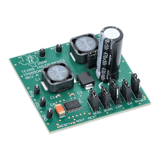
SLIU003 – October 2009 TPS55065EVM User's Guide Introduction The Texas Instruments TPS55065EVM evaluation module (EVM) helps designers evaluate the operation and performance of the TPS55065 Switch Mode Power Supply – Buck Regulator. The EVM contains one dc/dc converter (see Table Table 1. -
Page 6: Setup
The input voltage range for the converter is 1.5 V to 40 V. The input voltage must be at least 5 V during start up. TPS55065EVM User's Guide SLIU003 – October 2009 Submit Documentation Feedback Copyright © 2009, Texas Instruments Incorporated... -
Page 7: Operation
8, and Figure 9 show the board layout for the TPS55065EVM PWB. The EVM offers resistors, capacitors, and jumpers to program the switch pin slew rate and regulator turn-on Delay. Jumpers are also provided to enable the device and to enable the low-power mode option. -
Page 8: Bottom Assembly Layer
Board Layout www.ti.com Figure 7. Bottom Assembly Layer Figure 8. Top Layer Routing TPS55065EVM User's Guide SLIU003 – October 2009 Submit Documentation Feedback Copyright © 2009, Texas Instruments Incorporated... -
Page 9: Bottom Layer Routing
Board Layout www.ti.com Figure 9. Bottom Layer Routing SLIU003 – October 2009 TPS55065EVM User's Guide Submit Documentation Feedback Copyright © 2009, Texas Instruments Incorporated... -
Page 10: Schematic
Schematic www.ti.com Schematic Figure 10. TPS55065EVM Schematic TPS55065EVM User's Guide SLIU003 – October 2009 Submit Documentation Feedback Copyright © 2009, Texas Instruments Incorporated... - Page 11 Schematic www.ti.com Table 2. TPS55065EVM Bill of Materials COUNT REF DES DESCRIPTION SIZE PART NO. Capacitor, ceramic, 4.7nF, C1, C2 0603 muRata GRM188R71H472KA01B 50V, 10% Capacitor, ceramic, 470nF, 0603 muRata GRM188R71C474KA88B 16V, 10% Capacitor, ceramic, 100nF, C4, C7 0603 muRata...
- Page 12 EVALUATION BOARD/KIT IMPORTANT NOTICE Texas Instruments (TI) provides the enclosed product(s) under the following conditions: This evaluation board/kit is intended for use for ENGINEERING DEVELOPMENT, DEMONSTRATION, OR EVALUATION PURPOSES ONLY and is not considered by TI to be a finished end-product fit for general consumer use. Persons handling the product(s) must have electronics training and observe good engineering practice standards.
- Page 13 IMPORTANT NOTICE Texas Instruments Incorporated and its subsidiaries (TI) reserve the right to make corrections, modifications, enhancements, improvements, and other changes to its products and services at any time and to discontinue any product or service without notice. Customers should obtain the latest relevant information before placing orders and should verify that such information is current and complete.
Need help?
Do you have a question about the TPS55065EVM and is the answer not in the manual?
Questions and answers