
Related Manuals for Texas Instruments TPS53515EVM-PWR587


Summary of Contents for Texas Instruments TPS53515EVM-PWR587
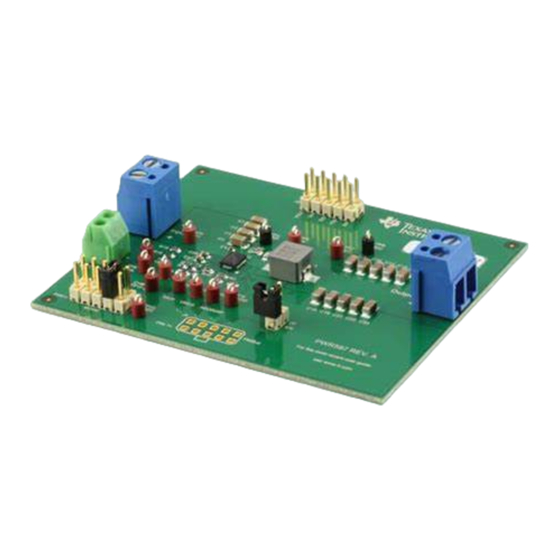
- Page 1 High Performance 12-A, Single-Synchronous, Step-Down Converter Using the TPS53515EVM- PWR587 User's Guide Literature Number: SLUUAS1 October 2013...
- Page 2 1.2-V output at up to 12 A from a 12-V input bus. Description The TPS53515EVM-PWR587 is designed for a regulated 12-V bus to produce a regulated 1.2-V output at up to 12 A of load current. The TPS53515EVM-PWR587 is designed to demonstrate the TPS53515 device in a typical low-voltage application while providing a number of test points to evaluate the performance of the TPS53515 device.
- Page 3 Electrical Performance Specifications www.ti.com Electrical Performance Specifications Table 1. TPS53515EVM-PWR587 Electrical Performance Specifications PARAMETER TEST CONDITIONS UNITS Input Characteristics Voltage range Maximum input current VIN = 5 V, Io = 8 A No load input current VIN = 12 V, Io = 0 A with auto-skip mode...
- Page 4 TPS53915 TPS53513 TPS53515 PIN 26 ALERT# PIN 27 GND1 GND1 PIN 28 GND2 GND2 Figure 1. TPS53515EVM-PWR587 Schematic High Performance 12-A, Single-Synchronous, Step-Down Converter Using the SLUUAS1 – October 2013 TPS53515EVM-PWR587 Submit Documentation Feedback Copyright © 2013, Texas Instruments Incorporated...
- Page 5 The minimum recommended wire size is 2× AWG number 14, with the total length of wire less than 4 feet (2 feet output, 2 feet return). SLUUAS1 – October 2013 High Performance 12-A, Single-Synchronous, Step-Down Converter Using the TPS53515EVM-PWR587 Submit Documentation Feedback Copyright © 2013, Texas Instruments Incorporated...
- Page 6 1. Connect the load to J3 and set the load to constant-resistance-mode to sink 0 ADC before VIN is applied. 2. Connect the voltmeter V2 at TP7 (VOUT) and TP9 (GND) to measure the output voltage. High Performance 12-A, Single-Synchronous, Step-Down Converter Using SLUUAS1 – October 2013 the TPS53515EVM-PWR587 Submit Documentation Feedback Copyright © 2013, Texas Instruments Incorporated...
- Page 7 9 to 10 pin shorted Auto-skip mode with 1× RC time constant Default setting. The device enters FCCM after PGOOD goes high. SLUUAS1 – October 2013 High Performance 12-A, Single-Synchronous, Step-Down Converter Using the TPS53515EVM-PWR587 Submit Documentation Feedback Copyright © 2013, Texas Instruments Incorporated...
- Page 8 11. Decrease the load to 0 A 12. Decrease VIN to 0 V. Control-Loop Gain and Phase-Measurement Procedure The TPS53515EVM-PWR587 contains a 10-Ω series resistor in the feedback loop for loop response analysis. 1. Set up the EVM as described in...
- Page 9 Equipment Shutdown Follow these steps when shutting down the equipment. 1. Shut down load 2. Shut down VIN SLUUAS1 – October 2013 High Performance 12-A, Single-Synchronous, Step-Down Converter Using the TPS53515EVM-PWR587 Submit Documentation Feedback Copyright © 2013, Texas Instruments Incorporated...
- Page 10 EVM Assembly Drawing and PCB Layout www.ti.com EVM Assembly Drawing and PCB Layout The following figures show the design of the TPS53515EVM-PWR587 printed circuit board (see Figure Figure Figure Figure Figure Figure Figure 10, and Figure 11). The EVM has been designed using a six-layer, 2-oz copper-circuit board.
- Page 11 EVM Assembly Drawing and PCB Layout www.ti.com Figure 6. TPS53515EVM-587 Top Layer, Copper Figure 7. TPS53515EVM-587 Layer Two, Copper SLUUAS1 – October 2013 High Performance 12-A, Single-Synchronous, Step-Down Converter Using the TPS53515EVM-PWR587 Submit Documentation Feedback Copyright © 2013, Texas Instruments Incorporated...
- Page 12 EVM Assembly Drawing and PCB Layout www.ti.com Figure 8. TPS53515EVM-587 Layer Three, Copper Figure 9. TPS53515EVM-587 Layer Four, Copper High Performance 12-A, Single-Synchronous, Step-Down Converter Using SLUUAS1 – October 2013 the TPS53515EVM-PWR587 Submit Documentation Feedback Copyright © 2013, Texas Instruments Incorporated...
- Page 13 EVM Assembly Drawing and PCB Layout www.ti.com Figure 10. TPS53515EVM-587 Layer Five, Copper Figure 11. TPS53515EVM-587 Bottom Layer, Copper SLUUAS1 – October 2013 High Performance 12-A, Single-Synchronous, Step-Down Converter Using the TPS53515EVM-PWR587 Submit Documentation Feedback Copyright © 2013, Texas Instruments Incorporated...
- Page 14 0.1 × 0.1 inch 5001 Keystone IC, High Performance, 12-A Single Sync. Step-Down Converter with TPS53515RVE TPS53515RVE PMBus. High Performance 12-A, Single-Synchronous, Step-Down Converter Using the SLUUAS1 – October 2013 TPS53515EVM-PWR587 Submit Documentation Feedback Copyright © 2013, Texas Instruments Incorporated...
- Page 15 Any exceptions to this are strictly prohibited and unauthorized by Texas Instruments unless user has obtained appropriate experimental/development licenses from local regulatory authorities, which is responsibility of user including its acceptable authorization.
- Page 16 FCC Interference Statement for Class B EVM devices This equipment has been tested and found to comply with the limits for a Class B digital device, pursuant to part 15 of the FCC Rules. These limits are designed to provide reasonable protection against harmful interference in a residential installation. This equipment generates, uses and can radiate radio frequency energy and, if not installed and used in accordance with the instructions, may cause harmful interference to radio communications.
- Page 17 Also, please do not transfer this product, unless you give the same notice above to the transferee. Please note that if you could not follow the instructions above, you will be subject to penalties of Radio Law of Japan. Texas Instruments Japan Limited (address) 24-1, Nishi-Shinjuku 6 chome, Shinjuku-ku, Tokyo, Japan http://www.tij.co.jp...
- Page 18 FDA Class III or similar classification, then you must specifically notify TI of such intent and enter into a separate Assurance and Indemnity Agreement. Mailing Address: Texas Instruments, Post Office Box 655303, Dallas, Texas 75265 Copyright © 2013, Texas Instruments Incorporated...
- Page 19 IMPORTANT NOTICE Texas Instruments Incorporated and its subsidiaries (TI) reserve the right to make corrections, enhancements, improvements and other changes to its semiconductor products and services per JESD46, latest issue, and to discontinue any product or service per JESD48, latest issue.
- Page 20 Mouser Electronics Authorized Distributor Click to View Pricing, Inventory, Delivery & Lifecycle Information: Texas Instruments TPS53515EVM-587...
Need help?
Do you have a question about the TPS53515EVM-PWR587 and is the answer not in the manual?
Questions and answers