Advertisement
www.ti.com
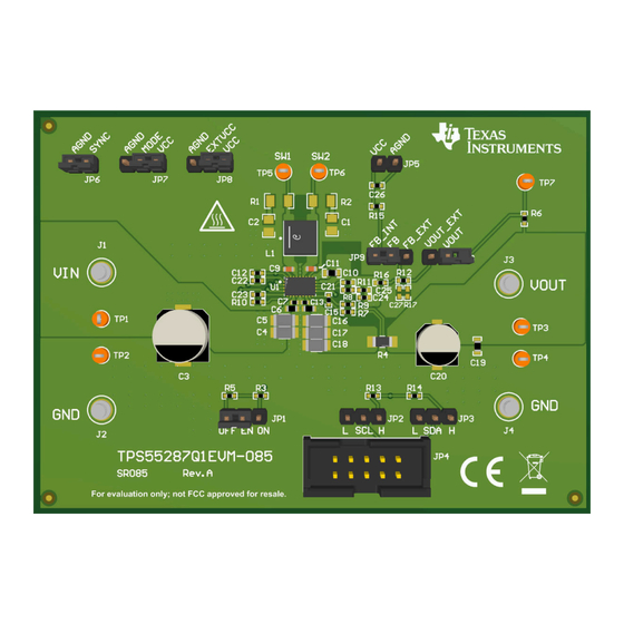
EVM User's Guide: TPS55287Q1EVM-085
TPS55287-Q1 Buck-Boost Converter Evaluation Module
Description
The TPS55287Q1EVM-085 is designed to
demonstrate the features and functionality of the
TPS55287-Q1 device, which is a high-performance,
high-efficiency synchronous buck-boost converter with
2
I
C interface. The factory default settings of the
TPS55287Q1EVM allow the operation with an input
voltage range from 3V to 36V. All these features
bring flexibility and design optimization for overall
performance, as well as BOM optimization and design
cost.
Get Started
1. Order the EVM at ti.com.
2. Read the user's guide carefully.
3. Prepare the bench setup per instructions. Take
precautions to prevent damage by ESD when
handling the EVM.
4. Power up the EVM by following the recommended
steps.
5. Run tests and measurements. Take cautions of
high voltage and hot temperature produced by the
EVM during test.
SLVUCZ5 – JULY 2024
Submit Document Feedback
Features
•
Wide input and output voltage range
•
Programmable power supply (PPS) support
2
•
I
C interface
•
Programmable output voltage from 0.8V to 22V
with 10mV step
•
Programmable output current limit up to 3.15A with
50mA step
•
Forced discharge function
•
User flexibilities in optimizing loop compensation
•
Programmable PFM and FPWM mode at light load
•
Optional programmable spread spectrum
•
Adjustable output voltage compensation for
voltage droop over the cable
•
Rich protection features
•
Small solution-size
Applications
•
Automotive USB charge
•
Wireless charger
•
Automotive media hub
•
ADAS domain controller
•
Automotive cluster display
•
Headlight,
Copyright © 2024 Texas Instruments Incorporated
rear light
TPS55287-Q1 Buck-Boost Converter Evaluation Module
Description
1
Advertisement
Table of Contents

Related Manuals for Texas Instruments TPS55287-Q1


Summary of Contents for Texas Instruments TPS55287-Q1
- Page 1 • Wide input and output voltage range demonstrate the features and functionality of the • Programmable power supply (PPS) support TPS55287-Q1 device, which is a high-performance, • C interface high-efficiency synchronous buck-boost converter with • Programmable output voltage from 0.8V to 22V C interface.
-
Page 2: Kit Contents
0.8V to 22V with 10mV step and the output current limit is programmable up to 3.15A with 50mA step, which is a good choice for USB Power Delivery (USB PD) applications. The TPS55287-Q1 has adjustable external loop compensation, programmable switching frequency, optional spread spectrum and rich protection features. -
Page 3: Device Information
Evaluation Module Overview 1.4 Device Information The TPS55287-Q1 is a synchronous buck-boost converter which integrates four MOSFET switches, providing a compact device for a variety of applications, especially for USB Power Delivery (USB PD) application. The device has up to 36V input voltage capability. Through the I C interface, the output voltage can be programmed from 0.8V to 22V with 10mV step, and the output current limit can be programmed up to 3.15A with 50mA... - Page 4 To minimize the power dissipation of the internal LDO when both input voltage and output voltage are high, an external 5V power supply can be applied at the VCC pin to supply the TPS55287-Q1. Place a jumper across EXTVCC and AGND to set the device VCC source externally. The external 5V power supply must have at least 100mA output current capability and must be within the 4.75V to 5.5V regulation range.
-
Page 5: Test Procedure
Table 1-2. 8. Turn off the load and power supply. Then, turn on the load to discharge the output capacitors. SLVUCZ5 – JULY 2024 TPS55287-Q1 Buck-Boost Converter Evaluation Module Submit Document Feedback Copyright © 2024 Texas Instruments Incorporated... - Page 6 (0x74, 0x75) and connect the GUI with the device. After the GUI and device are connected, the GUI reads all eight registers and shows a notification (Figure 3-3). TPS55287-Q1 Buck-Boost Converter Evaluation Module SLVUCZ5 – JULY 2024 Submit Document Feedback Copyright © 2024 Texas Instruments Incorporated...
- Page 7 Figure 3-4. GUI User Interface of TPS55287Q1EVM-085 5. Click the Enable button (Figure 3-5). The default output voltage is 5V. Enable Button Figure 3-5. ENABLE Button SLVUCZ5 – JULY 2024 TPS55287-Q1 Buck-Boost Converter Evaluation Module Submit Document Feedback Copyright © 2024 Texas Instruments Incorporated...
- Page 8 (if applicable). Refer to the TPS55287-Q1 36V, 4A Buck-Boost Converter with I C Interface data sheet for a detailed description of the TPS55287-Q1 registers. Figure 3-7. GUI Register Map Screen TPS55287-Q1 Buck-Boost Converter Evaluation Module SLVUCZ5 – JULY 2024 Submit Document Feedback Copyright ©...
- Page 9 SYNC AGND 0.1uF 102k 11.3k AGND AGND AGND AGND MODE EXTVCC MODE EXTVCC AGND AGND AGND AGND AGND Figure 4-1. TPS55287Q1EVM-085 Schematic SLVUCZ5 – JULY 2024 TPS55287-Q1 Buck-Boost Converter Evaluation Module Submit Document Feedback Copyright © 2024 Texas Instruments Incorporated...
-
Page 10: Pcb Layouts
Hardware Design Files www.ti.com 4.2 PCB Layouts Figure 4-2. TPS55287Q1EVM-085 Top-Side Layout Figure 4-3. TPS55287Q1EVM-085 Inner Layer1 TPS55287-Q1 Buck-Boost Converter Evaluation Module SLVUCZ5 – JULY 2024 Submit Document Feedback Copyright © 2024 Texas Instruments Incorporated... - Page 11 Hardware Design Files Figure 4-4. TPS55287Q1EVM-085 Inner Layer2 Figure 4-5. TPS55287Q1EVM-085 Bottom-Side Layout SLVUCZ5 – JULY 2024 TPS55287-Q1 Buck-Boost Converter Evaluation Module Submit Document Feedback Copyright © 2024 Texas Instruments Incorporated...
- Page 12 CRF1206-FZ-R020ELF Bourns ±75ppm/°C Molded SMD SMD Embossed T/R 115k RES, 115 k, 1%, 0.063 W, AEC-Q200 Grade 0402 CRCW0402115KFKED Vishay-Dale 0, 0402 TPS55287-Q1 Buck-Boost Converter Evaluation Module SLVUCZ5 – JULY 2024 Submit Document Feedback Copyright © 2024 Texas Instruments Incorporated...
- Page 13 RES, 2.20, 1%, 0.25 W, AEC-Q200 Grade 0, 1206 ERJ-8RQF2R2V Panasonic 1206 3.00k RES, 3.00 k, 1%, 0.063 W, AEC-Q200 Grade 0402 CRCW04023K00FKED Vishay-Dale 0, 0402 SLVUCZ5 – JULY 2024 TPS55287-Q1 Buck-Boost Converter Evaluation Module Submit Document Feedback Copyright © 2024 Texas Instruments Incorporated...
-
Page 14: Additional Information
Additional Information www.ti.com 5 Additional Information 5.1 Trademarks All trademarks are the property of their respective owners. TPS55287-Q1 Buck-Boost Converter Evaluation Module SLVUCZ5 – JULY 2024 Submit Document Feedback Copyright © 2024 Texas Instruments Incorporated... - Page 15 STANDARD TERMS FOR EVALUATION MODULES Delivery: TI delivers TI evaluation boards, kits, or modules, including any accompanying demonstration software, components, and/or documentation which may be provided together or separately (collectively, an “EVM” or “EVMs”) to the User (“User”) in accordance with the terms set forth herein.
- Page 16 www.ti.com Regulatory Notices: 3.1 United States 3.1.1 Notice applicable to EVMs not FCC-Approved: FCC NOTICE: This kit is designed to allow product developers to evaluate electronic components, circuitry, or software associated with the kit to determine whether to incorporate such items in a finished product and software developers to write software applications for use with the end product.
- Page 17 www.ti.com Concernant les EVMs avec antennes détachables Conformément à la réglementation d'Industrie Canada, le présent émetteur radio peut fonctionner avec une antenne d'un type et d'un gain maximal (ou inférieur) approuvé pour l'émetteur par Industrie Canada. Dans le but de réduire les risques de brouillage radioélectrique à...
- Page 18 www.ti.com EVM Use Restrictions and Warnings: 4.1 EVMS ARE NOT FOR USE IN FUNCTIONAL SAFETY AND/OR SAFETY CRITICAL EVALUATIONS, INCLUDING BUT NOT LIMITED TO EVALUATIONS OF LIFE SUPPORT APPLICATIONS. 4.2 User must read and apply the user guide and other available documentation provided by TI regarding the EVM prior to handling or using the EVM, including without limitation any warning or restriction notices.
- Page 19 Notwithstanding the foregoing, any judgment may be enforced in any United States or foreign court, and TI may seek injunctive relief in any United States or foreign court. Mailing Address: Texas Instruments, Post Office Box 655303, Dallas, Texas 75265 Copyright © 2023, Texas Instruments Incorporated...
- Page 20 TI products. TI’s provision of these resources does not expand or otherwise alter TI’s applicable warranties or warranty disclaimers for TI products. TI objects to and rejects any additional or different terms you may have proposed. IMPORTANT NOTICE Mailing Address: Texas Instruments, Post Office Box 655303, Dallas, Texas 75265 Copyright © 2024, Texas Instruments Incorporated...
Need help?
Do you have a question about the TPS55287-Q1 and is the answer not in the manual?
Questions and answers