Table of Contents
Advertisement
Quick Links
(1)
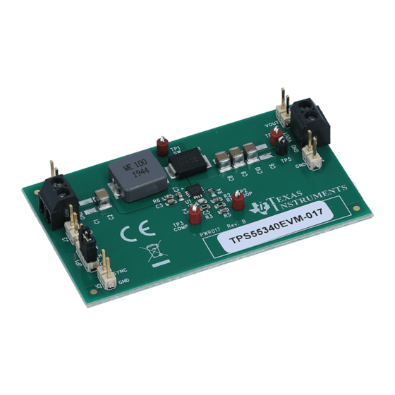
TPS55340EVM-017, 5-V to 12-V Input, 24-V Output Boost
Evaluation Module
This user's guide contains information for the TPS55340EVM-017 evaluation module (EVM) as well as the
TPS55340 DC/DC converter. The document includes the performance specifications, schematic, and the
bill of materials for the TPS55340EVM-017.
...................................................................................................................
1
2
3
4
5
Board Layout
6
Schematic and Bill of Materials
1
2
3
4
5
TPS55340EVM-017 V
6
7
8
9
10
11
TPS55340EVM-017 V
12
13
14
15
TPS55340EVM-017 Power Up With V
16
17
18
19
20
21
22
(1)
All trademarks are the property of their respective owners.
SLVU668B - April 2012 - Revised July 2019
Submit Documentation Feedback
.....................................................................................
..................................................................................................................
.....................................................................................................
................................................................................................................
...........................................................................................
.............................................................................................
= 5-V Transient Response
IN
= 12-V Transient Response
IN
.....................................................................................
= 5-V Output Ripple
IN
= 12-V Output Ripple
IN
.................................................................................
= 12-V Pulse-Skipping
IN
= 5-V Input Voltage Ripple
IN
= 12-V Input Voltage Ripple
IN
................................................................................
.................................................................................
IN
IN
...................................................................................
..........................................................................................
TPS55340EVM-017, 5-V to 12-V Input, 24-V Output Boost Evaluation Module
Copyright © 2012-2019, Texas Instruments Incorporated
SLVU668B - April 2012 - Revised July 2019
Contents
List of Figures
..................................................................
...................................................................
.....................................................................
...................................................................
............................................................................
...........................................................................
.........................................................................
....................................................................
.................................................................
.............................................................................
.............................................................................
...............................................................................
...........................................................................
...........................................................................
...............................................................................
User's Guide
2
2
3
3
12
15
4
5
5
6
6
7
7
8
8
9
9
10
10
11
11
12
13
13
14
14
15
15
1
Advertisement
Table of Contents

Related Manuals for Texas Instruments TPS55340EVM-017


Summary of Contents for Texas Instruments TPS55340EVM-017
-
Page 1: Table Of Contents
TPS55340EVM-017, 5-V to 12-V Input, 24-V Output Boost Evaluation Module This user’s guide contains information for the TPS55340EVM-017 evaluation module (EVM) as well as the TPS55340 DC/DC converter. The document includes the performance specifications, schematic, and the bill of materials for the TPS55340EVM-017. -
Page 2: Background
Output ripple voltage = 1.9 A mVpp Maximum efficiency TPS55340EVM-017, I = 800 mA 95.9% TPS55340EVM-017, 5-V to 12-V Input, 24-V Output Boost Evaluation Module SLVU668B – April 2012 – Revised July 2019 Submit Documentation Feedback Copyright © 2012–2019, Texas Instruments Incorporated... -
Page 3: Modifications
SW test point Test point between voltage divider network and output. Used for loop-response measurements. SLVU668B – April 2012 – Revised July 2019 TPS55340EVM-017, 5-V to 12-V Input, 24-V Output Boost Evaluation Module Submit Documentation Feedback Copyright © 2012–2019, Texas Instruments Incorporated... -
Page 4: Tps55340Evm-017 Efficiency
Output Voltage Load Regulation Figure 2 shows the load regulation for the EVM. TPS55340EVM-017, 5-V to 12-V Input, 24-V Output Boost Evaluation Module SLVU668B – April 2012 – Revised July 2019 Submit Documentation Feedback Copyright © 2012–2019, Texas Instruments Incorporated... -
Page 5: Tps55340Evm-017 Output Voltage Load Regulation
EVM with a 32-Ω (750-mA) load. Input Voltage (V) Figure 3. TPS55340EVM-017 Output Voltage Line Regulation SLVU668B – April 2012 – Revised July 2019 TPS55340EVM-017, 5-V to 12-V Input, 24-V Output Boost Evaluation Module Submit Documentation Feedback Copyright © 2012–2019, Texas Instruments Incorporated... -
Page 6: Tps55340Evm-017
(200 mA/div) Timebase (1.00 ms/div) Figure 5. TPS55340EVM-017 V = 12-V Transient Response TPS55340EVM-017, 5-V to 12-V Input, 24-V Output Boost Evaluation Module SLVU668B – April 2012 – Revised July 2019 Submit Documentation Feedback Copyright © 2012–2019, Texas Instruments Incorporated... -
Page 7: Tps55340Evm-017 Loop Response
SW (20.0 V/div) Timebase (1.00 µs/div) Figure 7. TPS55340EVM-017 V = 5-V Output Ripple SLVU668B – April 2012 – Revised July 2019 TPS55340EVM-017, 5-V to 12-V Input, 24-V Output Boost Evaluation Module Submit Documentation Feedback Copyright © 2012–2019, Texas Instruments Incorporated... -
Page 8: Tps55340Evm-017
AC Coupled (10 mV/div) SW (20.0 V/div) Timebase (1.00 µs/div) Figure 9. TPS55340EVM-017 DCM Output Ripple TPS55340EVM-017, 5-V to 12-V Input, 24-V Output Boost Evaluation Module SLVU668B – April 2012 – Revised July 2019 Submit Documentation Feedback Copyright © 2012–2019, Texas Instruments Incorporated... -
Page 9: Tps55340Evm-017
SW (20.0 V/div) Timebase (1.00 µs/div) Figure 11. TPS55340EVM-017 V = 5-V Input Voltage Ripple SLVU668B – April 2012 – Revised July 2019 TPS55340EVM-017, 5-V to 12-V Input, 24-V Output Boost Evaluation Module Submit Documentation Feedback Copyright © 2012–2019, Texas Instruments Incorporated... -
Page 10: Tps55340Evm-017
SW (20.0 V/div) (10.0 V/div) Timebase (2.00 ms/div) Figure 13. TPS55340EVM-017 Power Up With EN TPS55340EVM-017, 5-V to 12-V Input, 24-V Output Boost Evaluation Module SLVU668B – April 2012 – Revised July 2019 Submit Documentation Feedback Copyright © 2012–2019, Texas Instruments Incorporated... -
Page 11: Tps55340Evm-017 Power Down With En
SW (20.0 V/div) (10.0 V/div) Timebase (2.00 ms/div) Figure 15. TPS55340EVM-017 Power Up With V SLVU668B – April 2012 – Revised July 2019 TPS55340EVM-017, 5-V to 12-V Input, 24-V Output Boost Evaluation Module Submit Documentation Feedback Copyright © 2012–2019, Texas Instruments Incorporated... -
Page 12: Tps55340Evm-017 Power Down With
IC. TPS55340EVM-017, 5-V to 12-V Input, 24-V Output Boost Evaluation Module SLVU668B – April 2012 – Revised July 2019 Submit Documentation Feedback Copyright ©... -
Page 13: Tps55340Evm-017 Top-Side Assembly
Board Layout www.ti.com Figure 17. TPS55340EVM-017 Top-Side Assembly Figure 18. TPS55340EVM-017 Top-Side Layout SLVU668B – April 2012 – Revised July 2019 TPS55340EVM-017, 5-V to 12-V Input, 24-V Output Boost Evaluation Module Submit Documentation Feedback Copyright © 2012–2019, Texas Instruments Incorporated... -
Page 14: Tps55340Evm-017 Internal Layer-1 Layout
Figure 19. TPS55340EVM-017 Internal Layer-1 Layout Figure 20. TPS55340EVM-017 Internal Layer-2 Layout TPS55340EVM-017, 5-V to 12-V Input, 24-V Output Boost Evaluation Module SLVU668B – April 2012 – Revised July 2019 Submit Documentation Feedback Copyright © 2012–2019, Texas Instruments Incorporated... -
Page 15: Tps55340Evm-017 Bottom-Side Layout
SYNC SYNC COMP 10.0k 2.55k 100pF Not Populated 0.1uF Figure 22. TPS55340EVM-017 Schematic SLVU668B – April 2012 – Revised July 2019 TPS55340EVM-017, 5-V to 12-V Input, 24-V Output Boost Evaluation Module Submit Documentation Feedback Copyright © 2012–2019, Texas Instruments Incorporated... - Page 16 Schematic and Bill of Materials www.ti.com Bill of Materials Table 4 presents the bill of materials for the EVM. Table 4. TPS55340EVM-017 Bill of Materials RefDes Value Description Size Part Number Open Capacitor, ceramic, 35 V, X7R, 10% 1210 10 µF...
- Page 17 STANDARD TERMS FOR EVALUATION MODULES Delivery: TI delivers TI evaluation boards, kits, or modules, including any accompanying demonstration software, components, and/or documentation which may be provided together or separately (collectively, an “EVM” or “EVMs”) to the User (“User”) in accordance with the terms set forth herein.
- Page 18 Antenna types not included in this list, having a gain greater than the maximum gain indicated for that type, are strictly prohibited for use with this device. Revision History SLVU668B – April 2012 – Revised July 2019 Submit Documentation Feedback Copyright © 2012–2019, Texas Instruments Incorporated...
- Page 19 In a domestic environment this product may cause radio interference in which case the user may be required to take adequate measures. SLVU668B – April 2012 – Revised July 2019 Revision History Submit Documentation Feedback Copyright © 2012–2019, Texas Instruments Incorporated...
- Page 20 WHETHER CLAIMS ARISE UNDER STATUTE, REGULATION, OR THE LAW OF TORT, CONTRACT OR ANY OTHER LEGAL THEORY, AND EVEN IF THE EVM FAILS TO PERFORM AS DESCRIBED OR EXPECTED. Revision History SLVU668B – April 2012 – Revised July 2019 Submit Documentation Feedback Copyright © 2012–2019, Texas Instruments Incorporated...
- Page 21 Notwithstanding the foregoing, any judgment may be enforced in any United States or foreign court, and TI may seek injunctive relief in any United States or foreign court. Mailing Address: Texas Instruments, Post Office Box 655303, Dallas, Texas 75265 Copyright © 2019, Texas Instruments Incorporated SLVU668B –...
- Page 22 TI products. TI’s provision of these resources does not expand or otherwise alter TI’s applicable warranties or warranty disclaimers for TI products. Mailing Address: Texas Instruments, Post Office Box 655303, Dallas, Texas 75265 Copyright © 2019, Texas Instruments Incorporated...
Need help?
Do you have a question about the TPS55340EVM-017 and is the answer not in the manual?
Questions and answers