Table of Contents
Advertisement
Quick Links
Using the TPS54291EVM-431 A 12V Input, 3.3V 1.5A and
..................................................................................................................
1
1.1
1.2
1.3
2
....................................................................................................................
3
3.1
3.2
3.3
..................................................................................................................
4
4.1
4.2
4.3
4.4
4.5
4.6
5
5.1
5.2
5.3
6
7
1
2
3
4
5
6
7
8
9
10
11
12
13
1
SLVU356 - January 2010
Submit Documentation Feedback
1.2V 2.5A Synchronous Buck Converter
..........................................................................................................
.........................................................................................................
.............................................................................................................
..................................................................................
............................................................................................
............................................................................................
...........................................................................................................
...................................................................................................
.................................................................................
............................................................................................
..........................................................................................................
.......................................................................................
..................................................................................
............................................................................................................
List of Figures
........................................................................................
...........................................................................
List of Tables
Using the TPS54291EVM-431 A 12V Input, 3.3V 1.5A and 1.2V 2.5A
Copyright © 2010, Texas Instruments Incorporated
Contents
...........................................................
.............................................................
....................................................
.......................................
......................................................................
......................................................................
......................................................................
................................................................
....................................................
...................................................................
.................................................................
........................................................
..............................................................
..............................................................
......................................................
User's Guide
SLVU356 - January 2010
.....
...........................
Synchronous Buck Converter
2
2
2
2
3
4
5
5
5
6
6
7
9
10
10
10
10
11
11
12
12
16
4
8
9
9
11
11
12
12
13
13
14
14
15
3
1
Advertisement
Table of Contents

Related Manuals for Texas Instruments TPS54291EVM-431


Summary of Contents for Texas Instruments TPS54291EVM-431
-
Page 1: Table Of Contents
......................List of Materials List of Figures ..TPS54291EVM-431 Schematic (For Reference Only, See Table 4: Bill of Materials for Specific Values) ..............TPS54291EVM-431 Recommended Test Set-Up ......Output Ripple Measurement – Tip and Barrel using TP3 and TP4 or TP18 and TP19 .................. -
Page 2: Introduction
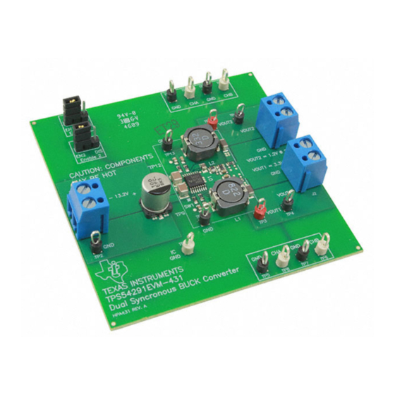
TPS54291EVM-431 is designed to use a regulated 12V (+10% /–20%) bus to produce two regulated power rails, 3.3V at 1.5A and 1.2V at 2.5A. TPS54291EVM-431 is designed to demonstrate the TPS54291 in a typical 12-V bus system while providing a number of test points to evaluate the performance of the TPS54291 in a given application. -
Page 3: Tps54291Evm-431 Electrical Performance Specifications
Operating Temperature Range = Min to Max, I = Min to Max °C SLVU356 – January 2010 Using the TPS54291EVM-431 A 12V Input, 3.3V 1.5A and 1.2V 2.5A Synchronous Buck Converter Submit Documentation Feedback Copyright © 2010, Texas Instruments Incorporated... -
Page 4: Schematic
Schematic Figure 1. TPS54291EVM-431 Schematic (For Reference Only, See Table 4: Bill of Materials for Specific Values) Using the TPS54291EVM-431 A 12V Input, 3.3V 1.5A and 1.2V 2.5A SLVU356 – January 2010 Synchronous Buck Converter Submit Documentation Feedback Copyright © 2010, Texas Instruments Incorporated... -
Page 5: Enable Jumpers (Jp1 And Jp2)
3.3.1 Input Voltage Monitoring (TP1 and TP2) TPS54291EVM-431 provides two test points for measuring the voltage applied to the module. This allows the user to measure the actual module voltage without losses from input cables and connectors. All input voltage measurements should be made between TP1 and TP2. To use TP1 and TP2, connect a voltmeter positive terminal to TP1 and negative terminal to TP2. -
Page 6: Test Set Up
3.3.5 TPS54291 IC Ground (TP11) TPS54291EVM-431 provides a test point for the IC ground. To measure IC pin voltages, connect the ground of the oscilloscope probe to TP11. 3.3.6 Channel 2 Switching Waveforms (TP12 and TP13) TPS54291EVM-431 provides a surface test pad and a local ground connection (TP13) for the monitoring of the channel 1 power stage switching waveform. -
Page 7: Equipment Setup
Equipment Setup Shown in Figure 2 is the basic test set up recommended to evaluate the TPS54291EVM-431. Note that although the return for J1, J2 and JP3 are the same system ground, the connections should remain separate as shown in Figure 4.2.1... -
Page 8: Tps54291Evm-431 Recommended Test Set-Up
1.2V @ 2.5A LOAD1 3.3V @ 1.5A Figure 2. TPS54291EVM-431 Recommended Test Set-Up Using the TPS54291EVM-431 A 12V Input, 3.3V 1.5A and 1.2V 2.5A SLVU356 – January 2010 Synchronous Buck Converter Submit Documentation Feedback Copyright © 2010, Texas Instruments Incorporated... -
Page 9: Start Up / Shut Down Procedure
Start Up / Shut Down Procedure 1. Increase V from 0V to 12Vdc SLVU356 – January 2010 Using the TPS54291EVM-431 A 12V Input, 3.3V 1.5A and 1.2V 2.5A Synchronous Buck Converter Submit Documentation Feedback Copyright © 2010, Texas Instruments Incorporated... -
Page 10: Output Ripple Voltage Measurement Procedure
Using the TPS54291EVM-431 A 12V Input, 3.3V 1.5A and 1.2V 2.5A SLVU356 – January 2010 Synchronous Buck Converter Submit Documentation Feedback Copyright ©... -
Page 11: Efficiency
= 0-2.5A OUT1 OUT1 OUT2 OUT2 Figure 6. TPS54291EVM-431 Output Voltage vs Load Current SLVU356 – January 2010 Using the TPS54291EVM-431 A 12V Input, 3.3V 1.5A and 1.2V 2.5A Synchronous Buck Converter Submit Documentation Feedback Copyright © 2010, Texas Instruments Incorporated... -
Page 12: Switch Node And Output Ripple Voltage
Figure 13 show the designs of the TPS54291EVM-431 printed circuit board. The EVM has been designed using a 4-Layer, 2oz copper-clad circuit board 3.0” × 3.0” with all components in a 0.86" × 1.28" active area on the top side and all active traces to the top and bottom layers to allow the user to easily view, probe and evaluate the TPS54291 control IC in a practical double-sided application. -
Page 13: Tps54291Evm-431 Silkscreen (Viewed From Top)
Figure 9. TPS54291EVM-431 Silkscreen (Viewed from Top) Figure 10. TPS54291EVM-431 Top Copper (Viewed from Top) SLVU356 – January 2010 Using the TPS54291EVM-431 A 12V Input, 3.3V 1.5A and 1.2V 2.5A Synchronous Buck Converter Submit Documentation Feedback Copyright © 2010, Texas Instruments Incorporated... -
Page 14: Tps54291Evm-431 Bottom Copper (X-Ray View From Top)
Figure 11. TPS54291EVM-431 Bottom Copper (X-Ray View from Top) Figure 12. TPS54291EVM-431 Internal 1 (X-Ray View from Top) Using the TPS54291EVM-431 A 12V Input, 3.3V 1.5A and 1.2V 2.5A SLVU356 – January 2010 Synchronous Buck Converter Submit Documentation Feedback... -
Page 15: Tps54291Evm-431 Internal 2 (X-Ray View From Top)
EVM Assembly Drawings and Layout www.ti.com Figure 13. TPS54291EVM-431 Internal 2 (X-Ray View from Top) SLVU356 – January 2010 Using the TPS54291EVM-431 A 12V Input, 3.3V 1.5A and 1.2V 2.5A Synchronous Buck Converter Submit Documentation Feedback Copyright © 2010, Texas Instruments Incorporated... -
Page 16: List Of Materials
0.100 929950-00 – PCB, 3 In × 3 In × 0.063 In HPA431 Using the TPS54291EVM-431 A 12V Input, 3.3V 1.5A and 1.2V 2.5A SLVU356 – January 2010 Synchronous Buck Converter Submit Documentation Feedback Copyright © 2010, Texas Instruments Incorporated... - Page 17 IMPORTANT NOTICE Texas Instruments Incorporated and its subsidiaries (TI) reserve the right to make corrections, modifications, enhancements, improvements, and other changes to its products and services at any time and to discontinue any product or service without notice. Customers should obtain the latest relevant information before placing orders and should verify that such information is current and complete.
- Page 18 Mouser Electronics Authorized Distributor Click to View Pricing, Inventory, Delivery & Lifecycle Information: Texas Instruments TPS54291EVM-431...
Need help?
Do you have a question about the TPS54291EVM-431 and is the answer not in the manual?
Questions and answers