Table of Contents
Advertisement
Quick Links
www.ti.com
User's Guide
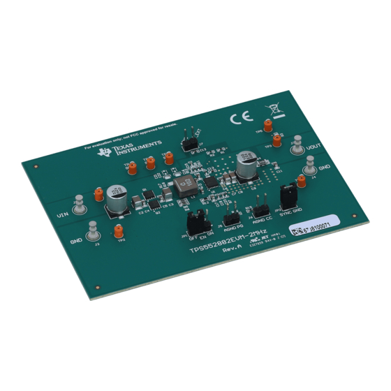
TPS552882EVM-2MHz Evaluation Module
This user's guide describes the characteristics, operation, and the use of the TPS552882EVM-2MHz evaluation
module (EVM). The EVM contains the TPS552882 device, which is a high-performance, high-efficiency
synchronous buck-boost converter which integrates two 16-A MOSFETs at the boost leg. The user's guide
includes EVM specifications, recommended test setup, test result, schematic diagram, bill of materials, and the
board layout.
1
Introduction.............................................................................................................................................................................2
1.1 Performance Specification.................................................................................................................................................
1.2 Modification........................................................................................................................................................................
2.1 Connector and Test Point Descriptions..............................................................................................................................
Configuration.........................................................................................................................................................2
3 Test Procedure........................................................................................................................................................................
4.1 Schematic..........................................................................................................................................................................
Materials...................................................................................................................................................................5
Layout......................................................................................................................................................................7
5 Revision History...................................................................................................................................................................
Figure 4-1. TPS552882EVM-2MHz Schematic...........................................................................................................................
Figure 4-2. TPS552882EVM-2MHz Top-Side Layout..................................................................................................................
Figure 4-5. TPS552882EVM-2MHz Bottom-Side Layout..........................................................................................................
Table 2-1. Connectors and Test Points........................................................................................................................................
Materials............................................................................................................................................................5
Trademarks
All other trademarks are the property of their respective owners.
SLVUBW5A - JUNE 2020 - REVISED OCTOBER 2020
Submit Document Feedback
ABSTRACT
Table of Contents
Descriptions.................................................................................................................2
Layout...................................................................................................................3
List of Figures
Layer1........................................................................................................................8
Layer2........................................................................................................................9
List of Tables
Summary..........................................................................................................................2
Copyright © 2020 Texas Instruments Incorporated
Table of Contents
TPS552882EVM-2MHz Evaluation Module
2
2
2
3
4
10
4
7
10
2
1
Advertisement
Table of Contents

Related Manuals for Texas Instruments TPS552882EVM-2MHz


Summary of Contents for Texas Instruments TPS552882EVM-2MHz
-
Page 1: Table Of Contents
TPS552882EVM-2MHz Evaluation Module ABSTRACT This user's guide describes the characteristics, operation, and the use of the TPS552882EVM-2MHz evaluation module (EVM). The EVM contains the TPS552882 device, which is a high-performance, high-efficiency synchronous buck-boost converter which integrates two 16-A MOSFETs at the boost leg. The user's guide includes EVM specifications, recommended test setup, test result, schematic diagram, bill of materials, and the board layout. -
Page 2: Introduction
2 Connector, Test Point and Jumper Descriptions This section describes how to properly connect, set up, and use the TPS552882EVM-2MHz. 2.1 Connector and Test Point Descriptions This EVM includes I/O connectors and test points as shown in Table 2-1. -
Page 3: Test Procedure
6. Turn off the load, turn off the power supply. Then turn on the load to discharge the output capacitors. 4 Schematic, Bill of Materials, and Board Layout This section provides the TPS552882EVM-2MHz schematic, bill of materials (BOM), and board layout. SLVUBW5A – JUNE 2020 – REVISED OCTOBER 2020... -
Page 4: Schematic
Schematic, Bill of Materials, and Board Layout www.ti.com 4.1 Schematic Figure 4-1 shows the EVM schematic. Figure 4-1. TPS552882EVM-2MHz Schematic TPS552882EVM-2MHz Evaluation Module SLVUBW5A – JUNE 2020 – REVISED OCTOBER 2020 Submit Document Feedback Copyright © 2020 Texas Instruments Incorporated... -
Page 5: Bill Of Materials
RES, 150 k, 1%, 0.063 W, AEC-Q200 Grade 0, 0402 0402 CRCW0402150KFKED Vishay-Dale RES, 0, 5%, 0.1 W, AEC-Q200 Grade 0, 0603 0603 CRCW06030000Z0EA Vishay-Dale SLVUBW5A – JUNE 2020 – REVISED OCTOBER 2020 TPS552882EVM-2MHz Evaluation Module Submit Document Feedback Copyright © 2020 Texas Instruments Incorporated... - Page 6 680pF ±5% 100V Ceramic Capacitor C0G,0603 (1608 Metric) 0603 GRT1885C2A681JA02D Murata R17, R18 RES, 1.0, 5%, 0.5 W, 1206 1206 CRM1206-JW-1R0ELF Bourns TPS552882EVM-2MHz Evaluation Module SLVUBW5A – JUNE 2020 – REVISED OCTOBER 2020 Submit Document Feedback Copyright © 2020 Texas Instruments Incorporated...
-
Page 7: Board Layout
Schematic, Bill of Materials, and Board Layout 4.3 Board Layout Figure 4-2 through Figure 4-5 illustrate the EVM board layouts. Figure 4-2. TPS552882EVM-2MHz Top-Side Layout SLVUBW5A – JUNE 2020 – REVISED OCTOBER 2020 TPS552882EVM-2MHz Evaluation Module Submit Document Feedback Copyright © 2020 Texas Instruments Incorporated... -
Page 8: Figure 4-3. Tps552882Evm-2Mhz Inner
Schematic, Bill of Materials, and Board Layout www.ti.com Figure 4-3. TPS552882EVM-2MHz Inner Layer1 TPS552882EVM-2MHz Evaluation Module SLVUBW5A – JUNE 2020 – REVISED OCTOBER 2020 Submit Document Feedback Copyright © 2020 Texas Instruments Incorporated... -
Page 9: Figure 4-4. Tps552882Evm-2Mhz Inner
Schematic, Bill of Materials, and Board Layout Figure 4-4. TPS552882EVM-2MHz Inner Layer2 SLVUBW5A – JUNE 2020 – REVISED OCTOBER 2020 TPS552882EVM-2MHz Evaluation Module Submit Document Feedback Copyright © 2020 Texas Instruments Incorporated... -
Page 10: Revision History
Revision History www.ti.com Figure 4-5. TPS552882EVM-2MHz Bottom-Side Layout 5 Revision History NOTE: Page numbers for previous revisions may differ from page numbers in the current version. Changes from Revision * (December 2020) to Revision A (October 2020) Page • Updated the numbering format for tables, figures, and cross-references throughout the document....2... - Page 11 STANDARD TERMS FOR EVALUATION MODULES Delivery: TI delivers TI evaluation boards, kits, or modules, including any accompanying demonstration software, components, and/or documentation which may be provided together or separately (collectively, an “EVM” or “EVMs”) to the User (“User”) in accordance with the terms set forth herein.
- Page 12 www.ti.com Regulatory Notices: 3.1 United States 3.1.1 Notice applicable to EVMs not FCC-Approved: FCC NOTICE: This kit is designed to allow product developers to evaluate electronic components, circuitry, or software associated with the kit to determine whether to incorporate such items in a finished product and software developers to write software applications for use with the end product.
- Page 13 www.ti.com Concernant les EVMs avec antennes détachables Conformément à la réglementation d'Industrie Canada, le présent émetteur radio peut fonctionner avec une antenne d'un type et d'un gain maximal (ou inférieur) approuvé pour l'émetteur par Industrie Canada. Dans le but de réduire les risques de brouillage radioélectrique à...
- Page 14 www.ti.com EVM Use Restrictions and Warnings: 4.1 EVMS ARE NOT FOR USE IN FUNCTIONAL SAFETY AND/OR SAFETY CRITICAL EVALUATIONS, INCLUDING BUT NOT LIMITED TO EVALUATIONS OF LIFE SUPPORT APPLICATIONS. 4.2 User must read and apply the user guide and other available documentation provided by TI regarding the EVM prior to handling or using the EVM, including without limitation any warning or restriction notices.
- Page 15 Notwithstanding the foregoing, any judgment may be enforced in any United States or foreign court, and TI may seek injunctive relief in any United States or foreign court. Mailing Address: Texas Instruments, Post Office Box 655303, Dallas, Texas 75265 Copyright © 2019, Texas Instruments Incorporated...
- Page 16 TI products. TI’s provision of these resources does not expand or otherwise alter TI’s applicable warranties or warranty disclaimers for TI products. Mailing Address: Texas Instruments, Post Office Box 655303, Dallas, Texas 75265 Copyright © 2020, Texas Instruments Incorporated...
Need help?
Do you have a question about the TPS552882EVM-2MHz and is the answer not in the manual?
Questions and answers