Table of Contents
Advertisement
Quick Links
www.ti.com
User's Guide
TPS563211 18-V Input, 3-A Output, 600-kHz,
Synchronous Buck Converter SOT583 Evaluation
Module
This user's guide contains information for the TPS563211 as well as support documentation for the
TPS563211EVM evaluation module. Included are the performance specifications, board layout, schematic, and
the list of materials of the TPS563211EVM.
1
Introduction.............................................................................................................................................................................2
2 Performance Specification Summary...................................................................................................................................
3
Modifications...........................................................................................................................................................................2
Configuration....................................................................................................................................................2
3.2 Output Voltage Setpoint.....................................................................................................................................................
Setup................................................................................................................................................................................3
4.1 Input/Output Connections..................................................................................................................................................
4.2 Start-Up Procedure............................................................................................................................................................
Layout...........................................................................................................................................................................5
5.1 Layout................................................................................................................................................................................
5.2 EVM Picture.......................................................................................................................................................................
6.1 Schematic..........................................................................................................................................................................
6.2 List of Materials..................................................................................................................................................................
7 Reference................................................................................................................................................................................
SLUUCC6 - SEPTEMBER 2020
Submit Document Feedback
ABSTRACT
Table of Contents
Reference........................................................................................................................8
TPS563211 18-V Input, 3-A Output, 600-kHz, Synchronous Buck Converter
Copyright © 2020 Texas Instruments Incorporated
Table of Contents
2
3
3
4
5
7
8
9
9
1
SOT583 Evaluation Module
Advertisement
Table of Contents

Related Manuals for Texas Instruments TPS563211


Summary of Contents for Texas Instruments TPS563211
-
Page 1: Table Of Contents
Synchronous Buck Converter SOT583 Evaluation Module ABSTRACT This user's guide contains information for the TPS563211 as well as support documentation for the TPS563211EVM evaluation module. Included are the performance specifications, board layout, schematic, and the list of materials of the TPS563211EVM. -
Page 2: Introduction
3.1 MODE Pin Configuration The TPS563211 has a MODE pin that can offer two different states of operation under light load conditions, and offer two options for the function of Pin 1. Table 3-1. MODE Pin Settings... -
Page 3: Output Voltage Setpoint
TP2 providing a convenient ground reference. TP3 is used to monitor the output voltage with TP4 as the ground reference. SLUUCC6 – SEPTEMBER 2020 TPS563211 18-V Input, 3-A Output, 600-kHz, Synchronous Buck Converter Submit Document Feedback SOT583 Evaluation Module... -
Page 4: Start-Up Procedure
VI (J1-2) and GND (J1-1). 3. Move the jumper at J3 (Enable control) pin 1 and 2 (EN and GND) to enable the output. TPS563211 18-V Input, 3-A Output, 600-kHz, Synchronous Buck Converter SLUUCC6 – SEPTEMBER 2020 SOT583 Evaluation Module Submit Document Feedback Copyright ©... -
Page 5: Board Layout
VIN, VOUT, and ground. Also on the top layer are connections for the pins of the TPS563211 and a large area filled with ground. Most of the signal traces are also located on the top side. - Page 6 Board Layout www.ti.com Figure 5-2. TPS563211EVM Top Layer Figure 5-3. TPS563211EVM Bottom Layer TPS563211 18-V Input, 3-A Output, 600-kHz, Synchronous Buck Converter SLUUCC6 – SEPTEMBER 2020 SOT583 Evaluation Module Submit Document Feedback Copyright © 2020 Texas Instruments Incorporated...
-
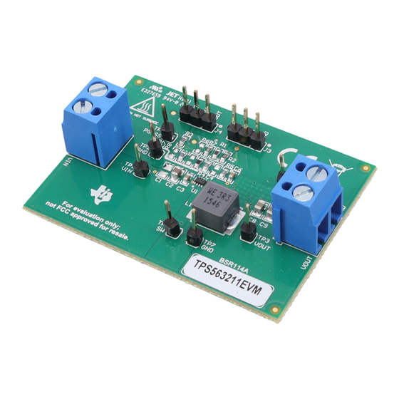
Page 7: Evm Picture
TPS563211EVM board top view and bottom view, respectively. Figure 5-4. TPS563211EVM Board Top View Figure 5-5. TPS563211EVM Board Bottom View SLUUCC6 – SEPTEMBER 2020 TPS563211 18-V Input, 3-A Output, 600-kHz, Synchronous Buck Converter Submit Document Feedback SOT583 Evaluation Module Copyright © 2020 Texas Instruments Incorporated... -
Page 8: Schematic, List Of Materials, And Reference
22uF 22uF 22uF 36.5k 10.0k 6.8nF 10.0k VOUT SH-J1 SH-J2 Figure 6-1. TPS563211EVM Schematic Diagram TPS563211 18-V Input, 3-A Output, 600-kHz, Synchronous Buck Converter SLUUCC6 – SEPTEMBER 2020 SOT583 Evaluation Module Submit Document Feedback Copyright © 2020 Texas Instruments Incorporated... -
Page 9: List Of Materials
RES, 0, 5%, 0.1 W, 0603 RC0603JR-070RL Yageo 7 Reference 1. Texas Instruments, TPS563211 4.2-V to 18-V Input, 3-A Synchronous Buck Converter in SOT583 Package SLUUCC6 – SEPTEMBER 2020 TPS563211 18-V Input, 3-A Output, 600-kHz, Synchronous Buck Converter Submit Document Feedback SOT583 Evaluation Module... - Page 10 STANDARD TERMS FOR EVALUATION MODULES Delivery: TI delivers TI evaluation boards, kits, or modules, including any accompanying demonstration software, components, and/or documentation which may be provided together or separately (collectively, an “EVM” or “EVMs”) to the User (“User”) in accordance with the terms set forth herein.
- Page 11 www.ti.com Regulatory Notices: 3.1 United States 3.1.1 Notice applicable to EVMs not FCC-Approved: FCC NOTICE: This kit is designed to allow product developers to evaluate electronic components, circuitry, or software associated with the kit to determine whether to incorporate such items in a finished product and software developers to write software applications for use with the end product.
- Page 12 www.ti.com Concernant les EVMs avec antennes détachables Conformément à la réglementation d'Industrie Canada, le présent émetteur radio peut fonctionner avec une antenne d'un type et d'un gain maximal (ou inférieur) approuvé pour l'émetteur par Industrie Canada. Dans le but de réduire les risques de brouillage radioélectrique à...
- Page 13 www.ti.com EVM Use Restrictions and Warnings: 4.1 EVMS ARE NOT FOR USE IN FUNCTIONAL SAFETY AND/OR SAFETY CRITICAL EVALUATIONS, INCLUDING BUT NOT LIMITED TO EVALUATIONS OF LIFE SUPPORT APPLICATIONS. 4.2 User must read and apply the user guide and other available documentation provided by TI regarding the EVM prior to handling or using the EVM, including without limitation any warning or restriction notices.
- Page 14 Notwithstanding the foregoing, any judgment may be enforced in any United States or foreign court, and TI may seek injunctive relief in any United States or foreign court. Mailing Address: Texas Instruments, Post Office Box 655303, Dallas, Texas 75265 Copyright © 2019, Texas Instruments Incorporated...
- Page 15 TI products. TI’s provision of these resources does not expand or otherwise alter TI’s applicable warranties or warranty disclaimers for TI products. Mailing Address: Texas Instruments, Post Office Box 655303, Dallas, Texas 75265 Copyright © 2020, Texas Instruments Incorporated...
Need help?
Do you have a question about the TPS563211 and is the answer not in the manual?
Questions and answers