Table of Contents
Advertisement
Quick Links
www.ti.com
EVM User's Guide: TPS562243EVM, TPS562246EVM
TPS562243 and TPS562246 Step-Down Converter
Evaluation Modules
Description
The TPS56224x is a single, D-CAP3
mode, synchronous buck converter with input voltage
ranging from 4.2V to 17V and supports up to 2A
continuous current. The device is optimized to operate
with minimum external component counts and low
standby current. The TPS562243 operates in Eco-
mode and the TPS562246 operates in FCCM mode.
The TPS56224xEVM is a fully assembled and tested
circuit for evaluating the TPS56224x converter.
SLUUCZ0 – APRIL 2024
Submit Document Feedback
Features
™
control
•
4.2V to 17V input voltage range
•
0.6V to 7V output voltage range
•
2A continuous output current
•
Eco/FCCM mode at light load
•
Fast transient D-CAP3 control mode
Applications
•
WLAN, Wi-Fi access
GFAST),
•
TV,
•
Appliances,
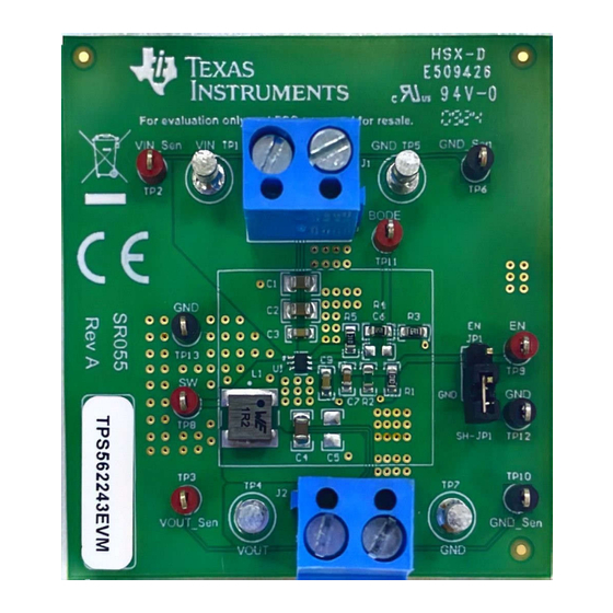
TPS562243EVM (Top View)
TPS562243 and TPS562246 Step-Down Converter Evaluation Modules
Copyright © 2024 Texas Instruments Incorporated
point,
modem (cable, DSL,
small business router
STB and DVR
video recorder
Description
1
Advertisement
Table of Contents

Related Manuals for Texas Instruments TPS562243EVM


Summary of Contents for Texas Instruments TPS562243EVM
- Page 1 Description EVM User's Guide: TPS562243EVM, TPS562246EVM TPS562243 and TPS562246 Step-Down Converter Evaluation Modules Description Features The TPS56224x is a single, D-CAP3 ™ control • 4.2V to 17V input voltage range mode, synchronous buck converter with input voltage • 0.6V to 7V output voltage range ranging from 4.2V to 17V and supports up to 2A...
-
Page 2: Kit Contents
Output Current (I ) Range TPS562243EVM = 4.2V to 17V 0A to 2A TPS562246EVM = 4.2V to 17V 0A to 2A TPS562243 and TPS562246 Step-Down Converter Evaluation Modules SLUUCZ0 – APRIL 2024 Submit Document Feedback Copyright © 2024 Texas Instruments Incorporated... - Page 3 Hardware 2 Hardware 2.1 Input and Output Connections The TPS562243EVM is provided with input and output connectors and test points as shown in Table 2-1. Figure shows connectors and jumpers placement on the TPS562243EVM board. A power supply capable of supplying 2A must be connected to J1 through a pair of 20-AWG wires. The load must be connected to J2 through a pair of 20-AWG wires.
-
Page 4: Output Voltage Setpoint
2. Apply appropriate input voltage to VIN (J1-2) and GND (J1-1). 3. Move the jumper at JP1 (Enable control) pin 2 and 1 (EN and GND) to enable the output. TPS562243 and TPS562246 Step-Down Converter Evaluation Modules SLUUCZ0 – APRIL 2024 Submit Document Feedback Copyright © 2024 Texas Instruments Incorporated... -
Page 5: Test Setup And Results
Implementation Results 3 Implementation Results 3.1 Test Setup and Results This section describes how to properly connect, set up, and use the TPS562243EVM. The section also includes test results typical for the evaluation modules and the following: • Load transient response •... - Page 6 SW = 5V/div VOUT = 1V/div 2ms/div Figure 3-3. TPS562243EVM Start-Up Relative to V Figure 3-4 shows the TPS562243EVM start-up waveform relative to enable (EN). The load is 2A. EN = 5V/div SW = 5V/div VOUT = 1V/div 800us/div Figure 3-4. TPS562243EVM Start-Up Relative to EN TPS562243 and TPS562246 Step-Down Converter Evaluation Modules SLUUCZ0 –...
- Page 7 SW = 5V/div VOUT = 1V/div 8ms/div Figure 3-5. TPS562243EVM Shutdown Relative to V Figure 3-6 shows the TPS562243EVM shutdown waveform relative to EN. The load is 2A. EN = 5V/div SW = 5V/div VOUT = 1V/div 800us/div Figure 3-6. TPS562243EVM Shutdown Relative to EN SLUUCZ0 –...
- Page 8 TPS562246EVM output voltage ripple. The output currents are as indicated. VOUT = 20mV/div (AC coupled) SW = 5V/div 1us/div Figure 3-7. TPS562243EVM Output Voltage Ripple, I = 2A VOUT = 20mV/div (AC coupled) SW = 5V/div 20us/div Figure 3-8. TPS562243EVM Output Voltage Ripple, I = 0.01A...
- Page 9 Implementation Results VOUT = 20mV/div (AC coupled) SW = 5V/div 1us/div Figure 3-9. TPS562246EVM Output Voltage Ripple, I = 0.01A SLUUCZ0 – APRIL 2024 TPS562243 and TPS562246 Step-Down Converter Evaluation Modules Submit Document Feedback Copyright © 2024 Texas Instruments Incorporated...
- Page 10 Hardware Design Files www.ti.com 4 Hardware Design Files 4.1 Schematic Figure 4-1 is the schematic for the TPS562243EVM. Figure 4-1. TPS562243EVM Schematic Diagram TPS562243 and TPS562246 Step-Down Converter Evaluation Modules SLUUCZ0 – APRIL 2024 Submit Document Feedback Copyright © 2024 Texas Instruments Incorporated...
-
Page 11: Pcb Layout
4-3, and Figure 4-4 show the board layout for the TPS562243EVM. The top layer contains the main power traces for VIN, VOUT, and ground. Connections for the pins of the TPS562243 and a large area filled with ground are also on the top layer. Most of the signal traces are also located on the top side. The input decoupling capacitors C1, C2, and C3 are located as close to the IC as possible. -
Page 12: Bill Of Materials
5 Additional Information 5.1 Trademarks ™ D-CAP3 is a trademark of Texas Instruments. All trademarks are the property of their respective owners. 6 Reference 1. Texas Instruments, TPS56224x 4.2V to 17V Input Voltage, 2A Synchronous Buck Converter in a SOT-563 Package data sheet. - Page 13 STANDARD TERMS FOR EVALUATION MODULES Delivery: TI delivers TI evaluation boards, kits, or modules, including any accompanying demonstration software, components, and/or documentation which may be provided together or separately (collectively, an “EVM” or “EVMs”) to the User (“User”) in accordance with the terms set forth herein.
- Page 14 www.ti.com Regulatory Notices: 3.1 United States 3.1.1 Notice applicable to EVMs not FCC-Approved: FCC NOTICE: This kit is designed to allow product developers to evaluate electronic components, circuitry, or software associated with the kit to determine whether to incorporate such items in a finished product and software developers to write software applications for use with the end product.
- Page 15 www.ti.com Concernant les EVMs avec antennes détachables Conformément à la réglementation d'Industrie Canada, le présent émetteur radio peut fonctionner avec une antenne d'un type et d'un gain maximal (ou inférieur) approuvé pour l'émetteur par Industrie Canada. Dans le but de réduire les risques de brouillage radioélectrique à...
- Page 16 www.ti.com EVM Use Restrictions and Warnings: 4.1 EVMS ARE NOT FOR USE IN FUNCTIONAL SAFETY AND/OR SAFETY CRITICAL EVALUATIONS, INCLUDING BUT NOT LIMITED TO EVALUATIONS OF LIFE SUPPORT APPLICATIONS. 4.2 User must read and apply the user guide and other available documentation provided by TI regarding the EVM prior to handling or using the EVM, including without limitation any warning or restriction notices.
- Page 17 Notwithstanding the foregoing, any judgment may be enforced in any United States or foreign court, and TI may seek injunctive relief in any United States or foreign court. Mailing Address: Texas Instruments, Post Office Box 655303, Dallas, Texas 75265 Copyright © 2023, Texas Instruments Incorporated...
-
Page 18: Important Notice
TI products. TI’s provision of these resources does not expand or otherwise alter TI’s applicable warranties or warranty disclaimers for TI products. TI objects to and rejects any additional or different terms you may have proposed. IMPORTANT NOTICE Mailing Address: Texas Instruments, Post Office Box 655303, Dallas, Texas 75265 Copyright © 2024, Texas Instruments Incorporated...
Need help?
Do you have a question about the TPS562243EVM and is the answer not in the manual?
Questions and answers