
Related Manuals for CTC Union IRC200-CCF40


Summary of Contents for CTC Union IRC200-CCF40
- Page 1 Quick Installation Guide IRC200-CCF40 4-Channel Contact Closure Media Converter sales@ctcu.com...
- Page 2 8F, No. 60 Zhouzi St., Neihu, Taipei 114, Taiwan T +886-2-26591021 F +886-2-26590237 E sales@ctcu.com H www.ctcu.com 2023 CTC Union Technologies Co., LTD. All trademarks are the property of their respective owners. Technical information in this document is subject to change without notice.
- Page 3 CTC Union Technologies makes no warranty, representation, or guarantee regarding the suitability of its products for any particular purpose, nor does CTC Union assume any liability arising out of the application or use of any product and specifically disclaims any and all liability, including without limitation any consequential or incidental damages.
-
Page 4: Table Of Contents
Table of Contents Introduction .................. 5 Management Features ..............5 Features ..................6 Specifications ................6 ....................6 PTICAL NTERFACE ....................6 ELAY ONTACT ......................7 OWER ...................... 7 ECHANICAL ....................7 NVIRONMENT Chassis Installation ..............8 Panels ................... 9 About SFP &... -
Page 5: Introduction
Always assume that fiber optic cables are connected to a laser light source. Management Features IRC200-CCF40 has an embedded processor which can be used to configure the device for stand-alone operation. When placed in a stand- alone chassis with DB9 console port, these devices support a text-based serial terminal with an easy to use menu system for configuration. -
Page 6: Features
Features Transmit a single contact closure in one or two directions Transmission distance up to 120KM 125VAC 0.5A or 30VDC 1A relay output Point-to-point transmission architecture Plug-and-play design to ensure ease of installation Hot-swappable rack module Specifications Optical Interface ... -
Page 7: Power
Power Operating Voltage: 8~15VDC Support power input reverse polarity protection Consumption: 4W (Max.) Mechanical Dimensions: 155mm (D) x 208mm (W) x 88mm (H) Weight: 200g Environment Operating Temperature: 0°C~50°C Storage Temperature: -10°C~85°C Humidity: 5%~95% (non-condensing) ... -
Page 8: Chassis Installation
Chassis Installation The contact closure media converter units can be placed in IRC200-CH01, IRC200-CH01M (1-slot with console) and IRC200-CH20 (20- slot) chassis. Figure 1. IRC200-CH20 Figure 3. IRC200-CH01M Figure 2. IRC200-CH01 Follow all ESD precautions when handling the card and SFP modules. -
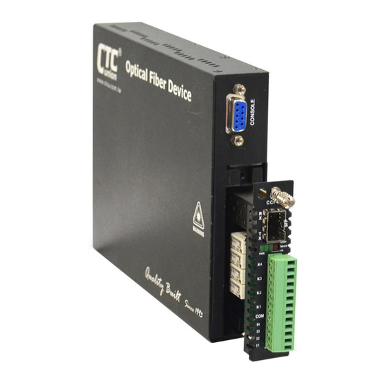
Page 9: Panels
Panels Figure 4. Front Panel Description Thumb screw SFP slot Power, System, Link, Test/Alarm indicators Removable terminal block for input contacts, COM and output contacts Input contacts (I1, I2, I3, I4), COM, output contacts (K1, K2, K3, K4) LED indicators Figure 5. -
Page 10: About Sfp & Sfp Installation
Remove the dust caps on SFP and patch cables only when ready to plug in optical cables. Installation CTC Union supplied SFP modules are of the Bale Clasp type. The bale clasp pluggable module has a bale clasp that secures the module into the SFP cage. -
Page 11: Led Indicators
LED Indicators Color State Descriptions Power on No power 1. Upgrade firmware (On/Off Green 100ms) Flash 2. Device is in disable mode (On: 1 second, Off: 4 seconds) Normal System Green System errors Link up and sync Link up but sync loss (On/Off Link Green Flash... -
Page 12: Console Management
Default username/password: admin/admin Connect the serial cable to the chassis' DB9. Run the terminal emulation program. About 3 seconds after being powered on, the IRC200-CCF40 will display the login menu as shown in the following example. ***************************************** CTC UNION TECHNOLOGIES CO.,LTD. -
Page 13: Main Menu Operation
After all of the parameter settings have been selected, go to the Main menu page and press "S" to store the settings in non-volatile RAM (NVR). ***************************************** CTC UNION TECHNOLOGIES CO.,LTD. IRC200-CCF40 Manager ***************************************** Ver:[ 1.000-1.002-1.000-0.000] [CH-01M <1>... -
Page 14: Channel Information And Configuration
Channel Information and Configuration << Channel 1 ~ 2 Information And Configuration >> +----+------------+------------+ +----+------------+------------+ | CH | Input (DI) | Output (K) | | CH | Input (DI) | Output (K) | +----+------------+------------+ +----+------------+------------+ 1 | Non Active | Non Active | 2 | Non Active | Non Active | +----+------------+------------+ +----+------------+------------+... -
Page 15: Fiber Information And Configuration
<1> Port Active: Enable or disable this fiber port. When disabled, this port is forced down regardless of the fiber connection <2> Loopback: Enable or disable loopback function. This IRC200-CCF40 media converter incorporates loop back features which allow loop back testing to confirm that the fiber optic connection is operating normally or not. - Page 16 ALS agent will turn off the transmitter. In this way the entire fiber will go dark. <D>DD Information: View digital diagnostics information of the inserted SFP transceiver. ***************************************** CTC UNION TECHNOLOGIES CO.,LTD. IRC200-CCF40 Manager ***************************************** Ver:[ 1.000-1.002-1.000-0.000] [CH-01M << SFP+ Digital Diagnostics >>...
-
Page 17: Device Information And Configuration
Device Information and Configuration << Device Information And Configuration >> Alarm: [LOS] <1> Device Active [Enable ] <2> Device Reset <3> Device Default <4> Input Debounce [Disable] [ESC] Go to previous menu. <1> Device Active: Enable or disable the device. When disabled, all LED indicators will be turned off except the power LED indicator. -
Page 18: Upgrading
Upgrading Stand-alone Firmware Upgrading via Xmodem The IRC200-CCF40 card may be firmware upgraded using XMODEM when placed in the chassis such as CH01M. The user may use serial terminal such as a notebook computer that has an RS232 port or via a commonly available USB to RS232 adapter. - Page 19 3. Start upgrading new Firmware image. 4. Check the Firmware version after completing the Firmware upgrade process. ***************************************** CTC UNION TECHNOLOGIES CO.,LTD. IRC200-CCF40 Manager ***************************************** Ver:[ 1.000-1.002-1.000-0.000] [CH-01M...
-
Page 20: Firmware Upgrading Via Nmc Card
Firmware Upgrading via NMC Card The IRC200-CCF40 card may be firmware upgraded when it is placed in the IRC200 with NMC management card. The user may use a local console connection to the NMC, a remote Telnet (IP) connection, or a Web based (HTTP) connection with any available browser. -
Page 21: Application
Output K1 K2 I3 I4 K3 K4 K1 K2 I3 I4 K3 K4 IRC200-CCF40 IRC200-CCF40 Fiber Fiber LOCAL DEVICE REMOTE DEVICE The K1 relay of the remote device reacts depending on signals received from the local device. When the I1 inputs from the local device are on (Relay closed), the KI relay of the remote device is also on (Relay closed) and vice versa. -
Page 22: Force Off" (Relay Open)
Input Output K1 K2 K1 K2 I3 I4 K3 K4 I3 I4 K3 K4 IRC200-CCF40 IRC200-CCF40 Fiber Fiber LOCAL DEVICE REMOTE DEVICE "Force On" (Relay Closed) When this mode is selected, it will force the relay of the remote device to close regardless of the input signals from the local device. -
Page 23: Fx Sync Loss: Off" (Relay Open)
Output K1 K2 K1 K2 I3 I4 K3 K4 I3 I4 K3 K4 IRC200-CCF40 IRC200-CCF40 Fiber Fiber LOCAL DEVICE REMOTE DEVICE In "FX Sync Loss: Off" mode, the relay of the remote device depends on the status fiber link. If the fiber sync is good, the relay is... -
Page 24: Fx Sync Loss: On" (Relay Closed)
Output K1 K2 K1 K2 I3 I4 K3 K4 I3 I4 K3 K4 IRC200-CCF40 IRC200-CCF40 Fiber Fiber LOCAL DEVICE REMOTE DEVICE In "FX Sync Loss: On" mode, the relay of the remote device depends on the status fiber link. If the fiber sync is good, the relay is... - Page 25 Version Date Description 2023/2/24 Preliminary version...
Need help?
Do you have a question about the IRC200-CCF40 and is the answer not in the manual?
Questions and answers