
Related Manuals for CTC Union IMC-1000S-PB


Summary of Contents for CTC Union IMC-1000S-PB
- Page 1 Quick Installation Guide IMC-1000S-PB 10/100/1000Base-T RJ-45 to 100/1000Base-X SFP with IEEE802.3af/at/bt PSE (90W) sales@ctcu.com...
- Page 2 8F, No. 60 Zhouzi St., Neihu, Taipei 114, Taiwan T +886-2-26591021 F +886-2-26590237 E sales@ctcu.com H www.ctcu.com 2022 CTC Union Technologies Co., LTD. All trademarks are the property of their respective owners. Technical information in this document is subject to change without notice.
-
Page 3: Table Of Contents
Table of Contents Introduction .................. 4 Package List ................. 4 Features ..................4 Specifications ................5 ....................... 5 TANDARDS LAN I ....................5 NTERFACE ....................5 IBER NTERFACE ..................5 OWER OVER THERNET ....................5 OWER UPPLY ...................... 6 ECHANICAL .................... -
Page 4: Introduction
2009 PoE standard also known as PoE+ or PoE plus, provides up to 30W of power. It is worth mentioning that IMC-1000S-PB can provide up to 90W per port through the use of all 4 pairs of category 5e cable. Thus, IMC-1000S-PB are ideal products for various applications especially used in industrial networking. -
Page 5: Specifications
Specifications Standards • IEEE Standards: IEEE802.3 (10Base-T), 802.3u (100Base-TX, 100Base- FX), 802.3ab (1000Base-T), IEEE802.3z (1000Base-X) • PoE Standards: IEEE802.3at, IEEE802.3af, IEEE802.3bt LAN Interface • 1 x 10/100/1000Mbps RJ-45 Port • Auto-Negotiation • Auto MDI/MDI-X • Jumbo Frames: 16K Bytes Fiber Interface •... -
Page 6: Mechanical
Mechanical • Water & Dust Proof: IP30 Protection • Dimensions: 80 mm (D) x 30 mm (W) x 115 mm (H) • Mounting: DIN-Rail, Wall Mount (Optional accessory) • Weight: 340g Environmental • Operating Temperature: -20°C~70°C • Storage Temperature: -40°C~85°C •... -
Page 7: Panels
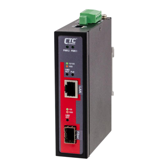
Panels Figure 2. Top Panel Figure 1. Front Panel Description SFP fiber slot LAN RJ-45 connector Link/ACT LED indicator for SFP interface Link/ACT LED indicator for LAN interface PoE LED indicator Power LED indicators Grounding connector Terminal block for power inputs (PWR1 & PWR2) DIP switch... -
Page 8: Lan & Fiber Interface
LAN & Fiber Interface IMC-1000S-PB PoE media converters have one electrical LAN port and one SFP fiber port on the front panel. The LAN port that utilizes shielded RJ-45 connector supports 10/100/1000M Ethernet transmissions; while the fiber port supports dual rate 100/1000M SFP transceivers. -
Page 9: Recommended Power And Ground Wiring Scheme
Recommended Power and Ground Wiring Scheme DC Power Connection A removable terminal block on the top panel provides two power connections. Power can be provided through the dual inputs from separate sources (PWR1 & PWR2). One power supply is enough to power up the device. -
Page 10: Earth Ground Connection
Earth Ground Connection An earth ground connector is provided on the top panel with an earth ground sign next to it. Grounding the device properly can help to release leakage of electricity to the earth safely so as to reduce unexpected influences from electromagnetic interference (EMI) and electromagnetic susceptibility (EMS). -
Page 11: Led Indicators
LED Indicators Color Status Definition Power LED indicator is lit and remains steady on when power is connected PWR1 Green and active at the PWR1/ PWR2 input PWR2 terminal connection. PWR1/PWR2 is not connected. The fiber link is up and operates at 100Mbps. -
Page 12: Dip Switch
DIP Switch 1 2 3 4 The DIP switch is provided on the top panel next to the terminal block for power inputs. There are four function switches available for use. See the table below for details. DIP No. Status Function Description Disable LFPT... -
Page 13: Installation
The PoE media converter with DIN rail bracket has a steel spring in the upper rail of the bracket. This spring is compressed for mounting and un-mounting by applying downward force. Figure 8. Mounting Figure 9. Un-mounting Application Diagram IMC-1000S-PB... - Page 14 Version Date Description 2022/2/14 Preliminary revision...
Need help?
Do you have a question about the IMC-1000S-PB and is the answer not in the manual?
Questions and answers