Table of Contents
Advertisement
Advertisement
Table of Contents

Related Manuals for CTC Union FRM220-NMC


Summary of Contents for CTC Union FRM220-NMC
- Page 1 Platform FRM220-NMC Network Management Controller...
- Page 3 Version 0.9r Jun 6, 2012 (Update) Version 0.9s Sep 28, 2012 (Update) Version 0.9t Oct 22, 2013 (Update) Version 0.9u Sep 11, 2015 (Update) Copyright © 2007-2015, CTC Union Technologies, Inc. All rights reserved. All specifications are subject to change without prior notice.
- Page 4 CTC Union Technologies assumes no responsibility, however, for possible errors or omissions, or for any consequences resulting from the use of the information contained herein. CTC Union Technologies reserves the right to make changes in its products or product specifications with the intent to improve function or design at any time and without notice and is not required to update this documentation to reflect such changes.
-
Page 5: Table Of Contents
Table of Contents Chapter 1 Introduction .................................. 9 1.0 Introduction ..................................9 1.1 Brief Functional Description ..............................9 1.2 Installing the NMC (CH20)..............................10 1.3 Card Options ..................................10 1.4 NMC (SNMP) ..................................10 1.4.1 NMC Introduction ............................... 10 1.4.2 FRM220 NMC Connections ............................11 1.4.3 FRM220 NMC Fault Handling ............................ - Page 6 Table of Contents A.6 FRM220-1000EDS Managed Gigabit Fiber Media Converter ..................68 A.6.1 Functional Details ............................... 69 A.6.2 Panel.................................... 69 A.6.3 Installation of SFP Modules ............................70 A.6.4 Provisioning by DIP (Stand-alone) ..........................70 A.6.5 Provisioning by NMC (Telnet) ........................... 71 A.6.6 Provisioning by NMC (Web) ............................
- Page 7 Table of Contents A.14 FRM220-10G-SSX 10Gbps 3R Fiber Transponder ...................... 133 A.14.1 Functional Details ..............................134 A.14.2 Installation of SFP Modules ........................... 134 A.14.3 Provisioning by NMC (Telnet) ..........................135 A.14.4 Provisioning by NMC (Web) ..........................137 A.14.5 Firmware Upgrade ..............................138 A.15 FRM220-MD40/80 CWDM Mux/DeMux ........................
- Page 8 Table of Contents A.29 FRM220-100A(S) 802.3ah OAM/IP In-band managed 10/100 Fiber Media Converter ..........189 A.29.1 Specifications ................................190 A.29.2 Management Features ............................. 190 A.29.3 Factory Reset Procedure ............................190 A.29.4 Panel..................................191 A.29.5 Installation of SFP Modules ............................ 191 A.29.6 Provisioning ................................
-
Page 9: Chapter 1 Introduction
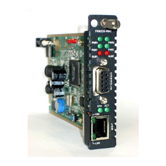
Metro LAN, or in enterprises, campus and central offices. The management module and interface card are both hot swappable, allowing online field replacement. All of the above mentioned chassis reserve one slot for installation of the FRM220-NMC network management controller and FRM220 converter card(s). The FRM220-NMC or Network Management Controller is installed in the first reserved slot, for local and remote management purposes. -
Page 10: Installing The Nmc (Ch20)
Chapter 1 Introduction 1.2 Installing the NMC (CH20) The front of the FRM220-CH20 contains the card slots. They are numbered 1 through 20, from left to right as viewed from the front. The typical configuration requires one NMC (Network Management Controller) card in slot number 1 and iAccess Platform cards in any other slot numbered 2 through 20. -
Page 11: Frm220 Nmc Connections
Chapter 1 Introduction Console Ethernet Electrical Electrical Electrical Fiber Fiber Electrical Fiber Fiber DCBus DCBus DCBus DCBus DCBus Logic Logic Logic Logic Logic RS485 Slot 1 Slot 2 Slot 4 Slot 20 Slot 3 Figure 1-3 FRM220 System Block Diagram 1.4.2 FRM220 NMC Connections DB9F to DB9M Console Cable, provided w/ NMC... -
Page 12: Nmc Card Fault And Replacement
Chapter 1 Introduction 1.4.4 NMC card Fault and Replacement If the NMC card should develop a fault, all media converter cards in the chassis will continue to run with their current configuration settings, with no negative effect to any traffic. The defective NMC may be pulled from the running chassis, without affecting any other media converter card. -
Page 13: Nmc Hardware Versions
Chapter 1 Introduction 1.4.7 NMC Hardware Versions There are currently three hardware versions of the Network Management Controller card. The differences are in Flash and/or SDRAM size on the card. Otherwise, the cards are identical. For each version, different software levels are required and maintained. -
Page 14: Chapter 2 Console Provisioning
Chapter 2 Console Provisioning 2.1 Introduction This chapter will go into the details of the specific provisioning and operation of the FRM220-NMC. Broken into two chapters, this chapter outlines the procedures and functions when using the serial console for configuration. -
Page 15: Console Mode
2.2.3 Terminal Pin Definition The console port of the FRM220-NMC is an RS-232 interface (DCE) that utilizes a DB9F connector. Use the configuration cable that is supplied with the iAccess or prepare a three wire DB9(F) to DB9(M) cable with the... -
Page 16: Terminal Login
The user password provides security to protect the system. From a Telnet connection, if you enter the wrong password three times, the security system will not allow any login again for 15 minutes. **************************************** *** CTC UNION TECHNOLOGIES CO., LTD. *** *** FRM220 NMC VER. 5.17 ***... -
Page 17: Tcp/Ip Configuration
The management configuration process is broken down into two logical steps. First the SNMP agent (the FRM220-NMC card itself) must be configured with an IP address, subnet mask and gateway IP. Second, the agent must be told who the network manager is, ie., the management workstation's IP address. Included in the second step are the community string settings and IP address to send the unsolicited trap messages (alarm messages). - Page 18 S: Use this key to confirm the settings, save and restart the SNMP daemon. ESC: Use the escape key to exit this menu without doing any changes. **************************************** *** CTC UNION TECHNOLOGIES CO., LTD. *** *** FRM220 NMC VER. 1.95 ***...
- Page 19 The SNMP protocol used in the FRM220-NMC is compliant with both SNMP V1 and SNMP V2C. The kernel in the FRM220-NMC is capable of supporting SNMP V3, however as of this writing that support has not yet been enabled. The major difference between SNMP V2C and V3 is the use of encryption layer for SNMP traffic.
-
Page 20: Using A Syslog Server
Syslog, in the FRM220-NMC, can be used for security auditing (login) as well as generalized informational (link down), analysis, and debugging (loop back) messages. The syslog function of the FRM220-NMC can be used to integrate log data into a central repository. -
Page 21: Chassis Information And Alarm Setup
Fault states for local and remote converters. The alarms must also be configured for NMC to send SNMP traps. From the main menu of the FRM220, press the '1' (one) key to enter the NMC & Chassis configuration. **************************************** *** CTC UNION TECHNOLOGIES CO., LTD. *** *** FRM220 NMC VER. 5.17 ***... - Page 22 At the same time, Alarm#2 will be triggered if any local copper or fiber link, Far End Fault or remote power has failure. The system is designed to allow very flexible use of the two dry contact alarms through customized monitoring schemes. **************************************** *** CTC UNION TECHNOLOGIES CO., LTD. *** *** FRM220 NMC VER. 5.17 *** ****************************************...
-
Page 23: User Password Setup
Serial console cable (DB9M to DB9F) [not required if performing by Telnet or Web] d. Ethernet UTP cables e. FRM220-NMC-R1, R2 or R3 latest version kernel and romfs file system f. Free TFTP server for Windows® (Ph. Jounin TFTP32) 2.2.9.3 Equipment Setup... - Page 24 The following screens will show the detailed procedures to setup the networking for the NMC and prepare for TFTP upgrade of the SNMP. Once the console port is connected to a terminal, the following screen will display. **************************************** *** CTC UNION TECHNOLOGIES CO., LTD. *** *** FRM220 NMC VER. 5.17 *** ****************************************...
- Page 25 Chapter 2 Provisioning Ping the NMC from the TFTP server PC and be sure there is a response. Make sure the upgrade file(s) are in the same folder as the TFTP server program. Start the TFTP server on the connected PC. In our example, we are using the free tftp32 TFTP server.
- Page 26 This completes the NMC upgrade procedure. Note: When CTC Union releases an update, a 'package' will be generated that includes all required code, the TFTP server application, a detailed upgrade procedure in PDF format specifically for the release and a release note listing the fixes or added features of the software.
-
Page 27: Chapter 3 Web Based Management
Note: CTC Union has an online demo unit placed on a public IP and answerable by DNS. We hope this demo will help our resellers to promote our product. End users may also find that evaluating our unit could lead to a decision to purchase our product. - Page 28 Chapter 3 Web Based Management 3.2.2.2 Home Page The Web GUI behaves just like any other web based application. The following graphic shows all of the areas that may be clicked for further configuration. Slots without any line card or without manageable line card will be shown as 'Empty'.
- Page 29 Chapter 3 Web Based Management 3.2.2.3 System Information Clicking on the "System" item will display an overview screen that allows setting system information, TFTP kernel and file system update, date & time setting, parameter management, and system backup.
- Page 30 Chapter 3 Web Based Management The System Information field provides the following settings: Target IP : This is the IPv4 dotted decimal IP address assigned to the NMC itself. Netmask : This value is set to the subnet address of the network to which the NMC is attached. Gateway IP : This IPv4 dotted decimal address is the default router to the network to which the NMC is attached.
- Page 31 Chapter 3 Web Based Management 3.2.2.4 Update Kernel and File System To update the NMC via the web interface, type in the kernel and file system image names and make sure those files are available from a TFTP server. Click the "Set Parameter" button. To update the kernel click the "Flash Kernel"...
- Page 32 Chapter 3 Web Based Management 3.2.2.6 System / Remote Area The "Remote Area" will give a graphic representation of all the remotely connected stand-alone converters. The following graphic shows all of the remote converters available through the in-band management. Click on any card to enter into the configuration graphic screen for that converter.
- Page 33 Chapter 3 Web Based Management 3.2.2.8 System / Properties The "Properties" page allows setting naming information for each local and remote converter along with the "Refresh" rate to redraw the browser screen. The name entries are also capable of supporting Unicode characters. The naming space allows up to 31 ASCII characters or 15 2-Byte (Chinese) characters.
- Page 34 Chapter 3 Web Based Management 3.3.2.9 SNMP + Chassis Click on "SNMP+Chassis" from the left hand window menu bar. Header The top header displays the chassis ID (0 for the master chassis, 1~9 for cascaded slave chassis), the slot number for NMC is always 1, NMC is always in local and the version displayed in the format h/w-s/w. In the above example, the NMC hardware version is 1.01 while the software version is 5.17 and kernel build 28580.
- Page 35 Chapter 3 Web Based Management Redundancy Mode Caution: Exercise extreme care and do not enable this mode unless you know what you are doing. The redundancy feature is a special operation mode designed only for FRM220-10/100i in-band managed cards. This mode allows the converter cards to be paired for redundancy. If either local or remote converter or fiber becomes disconnected, the data path will fallback to the secondary converter/fiber pair.
- Page 36 Chapter 3 Web Based Management Alarm 1 & 2 Settings Alarm 1 Mode can choose Disabled, By Powers, By User 1 or Active from the drop-down menu. If disabled, no condition will cause the Alarm 1 relay to close or become active. When selecting the "By Powers"...
- Page 37 Chapter 3 Web Based Management 3.3.2.10 SNMP + Chassis / Manager Setup Please note the following when setting the Manager's IP: 1. Using the word 'default' will allow any IP address to manage the rack. They will be assigned the access authority per the assigned community string and radio button setting, read-only or read-write.
- Page 38 Chapter 3 Web Based Management 3.3.2.12 Syslog Setup Syslog is a standard for logging program messages and is now standardized within the Syslog working group of the IETF. Syslog allows separation of the software that generates messages from the system that stores them and the software that reports and analyzes them.
-
Page 39: Chapter 4 Troubleshooting
Chapter 4 Troubleshooting Chapter 4 Troubleshooting 4.1 Network Settings 4.1.1 Review Agent Settings During unit startup, the "SNMP" LED will light as the agent boots up, and then it should blink at about one cycle per second after boot up and during normal operation. Refer to Chapter 2 section 2.2.5 TCP/IP Configuration for the SNMP agent settings. -
Page 40: Review Manager Settings
Chapter 4 Troubleshooting 4.1.2 Review Manager Settings For SNMP management software to connect to the NMC for management, the iAccess's NMC must be properly configured with the manager's IP address and authorized for read/write (via community string setting) and trap messages. Review the settings explained in 2.2.5 TCP/IP Configuration. If the management workstation is on a remote network, ensure it can also pass the ping test. -
Page 41: Appendix A. Frm220 Cards Options
Appendix A Appendix A. FRM220 Cards Options A.0 Introduction The FRM220 In-Band Managed Media Converter Chassis is designed to accept a variety of optical to electrical or optical to optical converter cards. As cards are added, this section will be updated with the relevant information for the new cards. - Page 42 Appendix A Operation Modes The default operational mode for the FRM220-10/100i is 'switch mode'. When the MC works in 'switch mode' mode, it does not begin to forward a packet to a destination port until after the entire packet is received. The latency therefore depends on the packet length. The maximum packet length supported is up to 2046 bytes in this mode.
- Page 43 Appendix A 3. Fault condition sent via OAM to far end 2. FX Link Down 4. FEF Led Lit Local Rx fiber Broken fiber local 1. fiber remote broken Remote Power 3. FEF LED lit 1. MC powered OFF Failure fiber 2.
-
Page 44: Block Diagram Of 10/100I
Appendix A A.1.2 Block Diagram of 10/100i 12VDC Reg. LEDs P RS485 driver Switch FIFO (For reference only) A.1.3 FRM220-10/100i Console Configuration From the main menu of the FRM220 NMC console, select the slot number containing the 10/100i line card. This Chassis ID:[00] Cascaded:[Yes] Monitored Chassis ID:[00]... -
Page 45: Frm220-10/100I Web Based Configuration
Appendix A Below is an example of managing the remote MC via OAM. This Chassis ID:[00] Cascaded:[Yes] Monitored Chassis ID:[00] SLOT #02 > FRM220-10/100I [Remote] [ Ver:1.100-1.279-0.000-0.000 ] Port Active:[Enable ] UTP Link:[Up Rx Active:[On ] <2>: Negotiation:[Auto <3>: Speed: [100 ] <4>: Duplex:... - Page 46 Appendix A Slot The slots in the chassis are numbered 1 ~ 20 from left to right when viewing from the front of the FRM220. The first slot is reserved for the NMC card. This card is required in every chassis, even in a cascaded stack. The slots for cards are numbered 2 ~ 20.
- Page 47 Appendix A Digital Diagnostics is an extended function of SFP modules that is specified in MSA (Multi-Source Agreements). Standard information that can be read from SFP includes the manufacture's name, model and serial number of the SFP. DD includes real time values for transmit and receive power and temperature within the SFP. Examples of SFP without and with DD function.
- Page 48 Appendix A Bandwidth Limiting This converter supports both ingress (UTP to Fiber) and egress (Fiber to UTP) bandwidth control in granularities of 32K or 512K. This provides a very flexible and controllable bandwidth usage through the media converter. The default setting is with no limiting. The above is an example of setting a 2Mbit bandwidth limit for both ingress and egress.
- Page 49 Appendix A A.1.4.3 UTP Information The basic link information can be viewed and the Ethernet parameters can be configured for forced mode here. The default setting is auto-negotiation enabled. Please be careful when setting manual or forced mode when connecting to another auto device to avoid performance killing duplex mismatch. Always connect auto to auto or set both connected interfaces to the same forced settings.
- Page 50 Appendix A A.1.4.5 Firmware Upgrade 1. From the "System" menu click the "Upgrade Line Card" button. 2. Select the card type radio button, which in this case is the FRM220-10/100i and FMC-10/100i 3. Select the slot to update. Selecting "All Slots" will upgrade all local and remote 10/100i cards. (this may take up to 15 minutes) 4.
-
Page 51: Frm220-10/100Is-2 Dual Channel In-Band Managed 10/100 Fiber Media Converter
Appendix A A.2 FRM220-10/100iS-2 Dual Channel In-band managed 10/100 Fiber Media Converter The FRM-10/100iS-2 (in-band converter) is a Dual Channel (2 converters in 1 card) In-band Managed (OAM) Fiber Ethernet media converter (MC) that supports 10Base-T or 100Base-TX and converts to 100Base-FX (fiber). The UTP side supports auto-negotiation or forced settings for speed and duplex by setting as well as auto-MDIX. -
Page 52: Frm220-10/100I-2E In-Band Managed 10/100 Fiber Media Converter
Appendix A A.3 FRM220-10/100i-2E In-band managed 10/100 Fiber Media Converter The FRM-10/100i-2E (in-band converter) is an In-band Managed (OAM) Fiber Ethernet media converter (MC) that supports 2 Ethernet channels of 10Base-T or 100Base-TX and converts to 100Base-FX (fiber). The UTP ports support auto-negotiation or forced settings for speed and duplex by setting as well as auto-MDIX. - Page 53 Appendix A Operation Modes The default operational mode for the FRM220-10/100i-2E is 'switch mode'. When the MC works in 'switch mode' mode, it does not begin to forward a packet to a destination port until after the entire packet is received. The latency therefore depends on the packet length. The maximum packet length supported is up to 2046 bytes in this mode.
- Page 54 Appendix A 3. Fault condition sent via OAM to far end 2. FX Link Down 4. FEF Led Lit Local Rx fiber Broken fiber local 1. fiber remote broken Remote Power 3. FEF LED lit 1. MC powered OFF Failure fiber 2.
-
Page 55: Block Diagram Of 10/100I-2E
Appendix A A.3.2 Block Diagram of 10/100i-2E 12VDC Reg. LEDs P RS485 driver Switch FIFO (For reference only) A.3.3 FRM220-10/100i-2e Console Configuration From the main menu of the FRM220 NMC console, select the slot number containing the 10/100i-2E line card. This Chassis ID:[00] Cascaded:[Yes] Monitored Chassis ID:[00]... -
Page 56: Frm220-10/100I-2E Web Based Configuration
Appendix A Below is an example of managing the remote MC via OAM. This Chassis ID:[00] Cascaded:[Yes] Monitored Chassis ID:[00] SLOT #09 > FRM220-10/100I-2E [Remote] [ Ver:1.100-1.001-0.000-0.000 ] Port Active:[Enable ] <2>: UTP 1 Information and Settings. <3>: UTP 2 Information and Settings. Link:[Up ] FEF:[Off ] Remote PWR:[OK... - Page 57 Appendix A Side Because most of the cards for the FRM220 series support in-band management, the "Side" parameter lets the user know if he is in the management screen for the "Local" or in the FRM220 chassis or for the "Remote" or fiber connected stand-alone converter.
- Page 58 Appendix A Port Active Use this pull-down to select whether to enable or disable the state of the media converter. When disabled, all LEDs on the unit and in the Web GUI will be extinguished. This function is not allowed when managing the remote converter and will be 'grayed out'.
- Page 59 Appendix A A.3.4.3 UTP Information The basic link information can be viewed and the Ethernet parameters can be configured for forced mode here. The default setting is auto-negotiation enabled. Please be careful when setting manual or forced mode when connecting to another auto device to avoid performance killing duplex mismatch. Always connect auto to auto or set both connected interfaces to the same forced settings.
- Page 60 Appendix A A.3.4.5 Firmware Upgrade 1. From the "System" menu click the "Upgrade Line Card" button. 2. Select the card type radio button, which in this case is the FRM220-10/100i-2E 3. Select the slot to update. Selecting "All Slots" will upgrade all local and remote 10/100i-2E cards. (this may take up to 15 minutes) 4.
- Page 61 Appendix A 8. Heed the warning messages!!!! 9. View the success results...
-
Page 62: Frm220-10/100A(S) 802.3Ah Oam/Ip In-Band Managed 10/100 Fiber Media Converter
Appendix A A.4 FRM220-10/100A(S) 802.3ah OAM/IP In-band managed 10/100 Fiber Media Converter This IEEE802.3ah OAM compliant copper to fiber Fast Ethernet solution is designed to make conversion between 10/100Base-TX and 100Base-FX with SC or ST connector. With its own built-in SNMP agent and GUI Web-based management or when placed in the managed FRM220, the Network administrator can monitor, configure and control the activity of each 802.3ah series line card. -
Page 63: Specifications
Appendix A A.4.1 Specifications Optical Interface Connector SFP cage (depending on model) Optical rate 125Mb/s Duplex mode Full duplex Fiber MM 50/125um, 62.5/125um SM 9/125um (depending on SFP) Distance MM 550M/2KM, SM 15/30/50/80/120KM (depending on SFP) ... -
Page 64: Panel
Figure A.4.1 Panel designations of FRM220-100AS-2 A.4.5 Installation of SFP Modules CTC Union supplied SFP modules are of the Bale Clasp type. The bale clasp pluggable module has a bale clasp that secures the module into the SFP cage. Inserting a Bale Clasp SFP Module into the Cage Step 1 Close the bale clasp upward before inserting the pluggable module. -
Page 65: Frm220-1000Ea(S) 802.3Ah In-Band Managed Gigabit Fiber Media Converter
Appendix A A.5 FRM220-1000EA(S) 802.3ah In-band managed Gigabit Fiber Media Converter This IEEE802.3ah OAM compliant copper to fiber Gigabit Ethernet solution is designed to make conversion between 10/100/1000Base-TX and 1000Base-SX/LX with SFP-LC connector. With SNMP agent and GUI Web- based management in the FRM220, the Network administrator can monitor, configure and control the activity of each 802.3ah series line card. -
Page 66: Functional Details
Appendix A A.5.1 Functional Details Ethernet The 1000EAS is based on a L2 switch chip which supports non-blocking switching fabric with up to 1024 MAC lookup filtering table and support for Egress tagging/untagging selectable per port in any combination using 802.1Q VLAN support for 4094 VIDs and BPDU handling for spanning tree protocol. -
Page 67: Factory Reset Procedure
The username and password are both reset to 'admin' if enabled. A.5.3.1 Installation of SFP Modules CTC Union supplied SFP modules are of the Bale Clasp type. The bale clasp pluggable module has a bale clasp that secures the module into the SFP cage. -
Page 68: Frm220-1000Eds Managed Gigabit Fiber Media Converter
Appendix A A.6 FRM220-1000EDS Managed Gigabit Fiber Media Converter The FRM220-1000EDS is a 4-port switch or dual channel (two in one) copper to fiber Gigabit Ethernet solution designed to make conversion between 10/100/1000Base-TX and 1000Base-SX/LX with SFP transceivers. With SNMP and Web-based management in the FRM220, the Network administrator can monitor, configure and control the activity of each card in the chassis. -
Page 69: Functional Details
Appendix A A.6.1 Functional Details Ethernet The 1000EDS is based on a L2 switch chip which supports non-blocking switching fabric with up to 1024 MAC lookup filtering table. There are also two 64 bit RMON counters per port that can be displayed through the management system of the FRM220-CH20 chassis. -
Page 70: Installation Of Sfp Modules
Appendix A A.6.3 Installation of SFP Modules CTC Union supplied SFP modules are of the Bale Clasp type. The bale clasp pluggable module has a bale clasp that secures the module into the SFP cage. A.6.3.1 Inserting a Bale Clasp SFP Module into the Cage Step 1 Close the bale clasp upward before inserting the pluggable module. -
Page 71: Provisioning By Nmc (Telnet)
Appendix A DIP SW 1 and DIP SW 2: (note: 1000ES-1 has one DIP switch for its LAN 1 port only. SW5 has no function.) (note2: 1000EDS has two DIP switches, DIPSW1 for LAN1 and DIPSW2 for LAN 2.) SW 1 SW 2 SW 3 Mode of LAN Port UTP/NWAY (auto) 1000/FULL (forced) - Page 72 Appendix A Description of Menu Settings <1> : Fiber 1 Displays information and settings for Port 1 fiber. <2> : Fiber 2 Displays information and settings for Port 2 fiber. This Chassis ID:[00] Cascaded:[Yes] Monitored Chassis ID:[00] SLOT #09 > FRM220-1000EDS [Local ] [ Ver:1.200-1.600-0.000-0.000 ] <<<...
- Page 73 Appendix A <1> : Port Active: The port can be disabled so that no traffic will pass. The default is with port enabled. <2> : Negotiation: The default is ‘Auto’ per 802.3u. Set to ‘Manual’ to configure forced mode <3> : Speed : The UTP supports 10, 100, 1000 speed setting if negotiation is set to manual.
-
Page 74: Provisioning By Nmc (Web)
Appendix A A.6.6 Provisioning by NMC (Web) The settings, described in the Telnet operation, are easily manipulated here in the Web GUI. From the top, the Fiber port 1, Fiber port 2, UTP port 3 and UTP port 4 have their information and settings. The Device Information box has the operation mode pull-down and the Auto Laser Shutdown settings. -
Page 75: Firmware Upgrade
Appendix A Lastly the ‘counters’ and SFP information is displayed at the bottom of the web page. The counters are 64 bit registers for in and out traffic, for each port. A.6.7 Firmware Upgrade 1. From the "System" menu click the "Upgrade Line Card" button. 2. - Page 76 Appendix A 7. Click the "OK" button to confirm. 8. Heed the warning messages!!!! 9. View the success results...
-
Page 77: Frm220-E1/T1 In-Band Managed G.703 E1/T1(Ds1) Fiber Modem
Appendix A A.7 FRM220-E1/T1 In-band managed G.703 E1/T1(DS1) Fiber Modem The FRM220-E1/T1 is a fiber modem transport for G.703 E1 or T1(DS1) transmission. The BNC model (E1 only) provides unbalanced 75 Ohm coaxial connections while the RJ-45 model provides balanced 100/120 Ohm connections over twisted pair wiring. -
Page 78: Functional Details
Appendix A A.7.1 Functional Details Fiber The E1/T1 fiber modem uses a proprietary scrambled NRZ optical line coding to provide extremely low BER for E1 over fiber. The electrical interface is an unbalanced 75 ohm for the BNC model or balanced twisted pair on industry standard USOC RJ48C wiring on a physical shielded RJ-45. -
Page 79: Installation Of Sfp Modules
Appendix A A.7.3 Installation of SFP Modules CTC Union supplied SFP modules are of the Bale Clasp type. The bale clasp pluggable module has a bale clasp that secures the module into the SFP cage. A.7.3.1 Inserting a Bale Clasp SFP Module into the Cage Step 1 Close the bale clasp upward before inserting the pluggable module. - Page 80 Appendix A Switch 1 settings DIP SW1 SW STATE Function E1/T1 Setting Line Code Setting HDB3(E1)/B8ZS(T1) Full or Fraction Setting Full E1/T1 Fractional E1/T1 Frame setting CCS(E1), D4(SF)(T1) CAS(e1), ESF(T1) CRC setting Disable Enable Auto transmitted AIS when Disable received signal loss setting. Enable E1/T1 transmitted timing setting Recovery from remote side...
- Page 81 Appendix A Switch 2 settings Use the switches 1~5 to set the nx64k rate For T1, the maximum is 24 timeslots For E1-CCS the maximum is 31 timeslots For E1-CAS the maximum is 30 timeslots DIP SW2 SW STATE Function Fraction timeslot number setting Full E1/T1 1 timeslot...
- Page 82 Appendix A Switch 3 settings After setting the required nx64k timeslot amount, set the starting timeslot number for the contiguous set of active timeslots. Do not use TS16 if E1-CAS is used For T1 there are no timeslots above TS24 DIP SW3 SW STATE Function...
-
Page 83: Provisioning By Nmc (Telnet)
Appendix A A.7.5 Provisioning by NMC (Telnet) When placed in the CH20 with NMC, this card can be configured through any of the NMC interfaces, including Telnet, Web GUI and SNMP. This Chassis ID:[00] Cascaded:[Yes] Monitored Chassis ID:[00] SLOT #18 > FRM220-E1/T1 [Local ] [ Ver:1.000-1.110-1.020-0.000 ] <1>... - Page 84 Appendix A E1/T1 and Fiber Loop Back Here is a review of the loop back functions available for the E1/T1 line card. Local loopback Remote Side Local Side Remote loopback Remote Side Local Side RRLB Request Remote loopback Remote Side Local Side E1/T1 Loop Back Functions Local...
-
Page 85: Provisioning By Nmc (Web)
Appendix A A.7.6 Provisioning by NMC (Web) The settings, described in the Telnet operation, are easily manipulated here in the Web GUI. From the top, the Fiber port, E1/T1 port, Function buttons and SFP information at the bottom. After making any changes, be sure to click the “Set Parameters” button. -
Page 86: Firmware Upgrade
Appendix A A.7.7 Firmware Upgrade 1. From the "System" menu click the "Upgrade Line Card" button. 2. Select the card type radio button, which in this case is the FRM220-E1/T1 3. Select the slot to update. Selecting "All Slots" will upgrade all local and remote E1/T1 cards. (this may take up to 15 minutes) 4. - Page 87 Appendix A 7. Click the "OK" button to confirm. 8. Heed the warning messages!!!! 9. View the success results...
-
Page 88: Frm220-Data In-Band Managed V.35, X.21, Rs-530/449/232 Fiber Modem
Appendix A A.8 FRM220-Data In-band managed V.35, X.21, RS-530/449/232 Fiber Modem The FRM220-DATA is a fiber modem for high-speed (up to 8.192Mbps) synchronous or low speed synchronous and asynchronous data transmissions (V.35, RS-232, RS-530, X.21 or RS-449) over fiber optical media. -
Page 89: Functional Details
Appendix A A.8.1 Functional Details Fiber The DATA fiber modem uses a proprietary scrambled NRZ optical line coding to provide extremely low BER for Serial Data over fiber. The electrical interface is software selectable between RS-530 (including X.21 and RS-449), V.35 or RS-232. The interface is also software selectable between DCE and DTE, which will eliminate using any special cross-over or null-MODEM cables. -
Page 90: Installation Of Sfp Modules
Appendix A A.8.3 Installation of SFP Modules CTC Union supplied SFP modules are of the Bale Clasp type. The bale clasp pluggable module has a bale clasp that secures the module into the SFP cage. A.8.3.1 Inserting a Bale Clasp SFP Module into the Cage Step 1 Close the bale clasp upward before inserting the pluggable module. - Page 91 Appendix A Switch 1 settings (Receive timing) SW STATE Function Receive Data Rate Select Group1 Group2 Group3 Group4 Group5 Group6 Group7 Group8 2112K 4160K 6208K 8256K 128K 2176K 4224K 6272K 8320K 112.5 192K 2240K 4288K 6336K 8384K 256K 2304K 4352K 6400K 8448K 320K...
- Page 92 Appendix A Switch 2 settings (Transmit timing) SW STATE Function Transmit Data Rate Select Group1 Group2 Group3 Group4 Group5 Group6 Group7 Group8 2112K 4160K 6208K 8256K 128K 2176K 4224K 6272K 8320K 112.5 192K 2240K 4288K 6336K 8384K 256K 2304K 4352K 6400K 8448K 320K...
- Page 93 Appendix A Switch 3 settings Use the switches 1~2 to set the DSR/DTR handshaking Use the switches 3~4 to set the CTS/RTS handshaking Use the switch 5 to set the ETC polarity Use the switch 6 to set the TC polarity Use the switch 7 to set the RC polarity Use the switch 8 to select the port setting as DCE or DTE.
-
Page 94: Provisioning By Nmc (Telnet)
Appendix A A.8.5 Provisioning by NMC (Telnet) When placed in the CH20 with NMC, this card can be configured through any of the NMC interfaces, including Telnet, Web GUI and SNMP. This Chassis ID:[00] Cascaded:[Yes] Monitored Chassis ID:[00] SLOT #16 > FRM220-DATAPORT [Local ] [ Ver:1.000-1.050-1.010-0.000 ] <1>... - Page 95 Appendix A Data Port Control Settings Menu ------------------------------------------------------------------------ Data Port Control Setting: <0>:DSR/DTR output setting[Constantly ON ]<1>:ETC polarity setting[Normal] <2>:CTS/RTS output setting[Constantly ON ]<3>:TC polarity setting[Normal] <4>:DCD output setting[Constantly ON <5>:RC polarity setting[Normal] ------------------------------------------------------------------------ Data Port and Fiber Loop Back Here is a review of the loop back functions available for the DATA line card.
-
Page 96: Provisioning By Nmc (Web)
Appendix A A.8.6 Provisioning by NMC (Web) The settings, described in the Telnet operation, are easily manipulated here in the Web GUI. From the top, the Fiber port, DATA port, Function buttons and SFP information (if any) at the bottom. After making any changes, be sure to click the “Set Parameters”... -
Page 97: Firmware Upgrade
Appendix A A.8.7 Firmware Upgrade 1. From the "System" menu click the "Upgrade Line Card" button. 2. Select the card type radio button, which in this case is the FRM220-DATA 3. Select the slot to update. Selecting "All Slots" will upgrade all local and remote DATA cards. (this may take up to 15 minutes) 4. - Page 98 Appendix A 7. Click the "OK" button to confirm. 8. Heed the warning messages!!!! 9. View the success results...
-
Page 99: Frm220-Serial/485 In-Band Managed Rs-485/422/232 Fiber Modem
Appendix A A.9 FRM220-Serial/485 In-band managed RS-485/422/232 Fiber Modem The FRM220-Serial/485 provides an Asynchronous Fiber Modem solution to extend RS-485 or RS-232 transmission distance up to 2km over multimode fiber or up to 120km over single mode fiber. The modem is equipped with multiple interface circuits for connection to RS-232 or RS-485/422 (2 or 4 wire, full or half duplex). -
Page 100: Functional Details
Appendix A A.9.1 Functional Details Fiber The Serial fiber modem uses a proprietary scrambled NRZ optical line coding to provide extremely low BER for Serial Data over fiber. The electrical interface is software selectable between RS-232 3-wire or 5-wire and RS-485 4-wire Full Duplex or 2-wire Half Duplex interface. -
Page 101: Installation Of Sfp Modules
Appendix A A.9.3 Installation of SFP Modules CTC Union supplied SFP modules are of the Bale Clasp type. The bale clasp pluggable module has a bale clasp that secures the module into the SFP cage. A.9.3.1 Inserting a Bale Clasp SFP Module into the Cage Step 1 Close the bale clasp upward before inserting the pluggable module. -
Page 102: Provisioning By Nmc (Telnet)
Appendix A Switch 1 settings DIP SW NO. SW State Function RS-422 4-Wire RS-485 2-Wire RS-232 with RTS/CTS 5-Wire RS-232 3-Wire RS-422 Transmit Termination OFF RS-422 Transmit Termination ON RS-485/RS-422 Receive Termination OFF RS-485/RS-422 Receive Termination ON RS-485/RS-422 Receive(B)(-) 1K ohm “pull down” OFF RS-485/RS-422 Receive(B)(-) 1K ohm “pull down”... -
Page 103: Provisioning By Nmc (Web)
Appendix A A.9.6 Provisioning by NMC (Web) The settings, described in the Telnet operation, are easily manipulated here in the Web GUI. From the top, the Fiber port, DATA port, Function buttons and SFP information (if any) at the bottom. After making any changes, be sure to click the “Set Parameters”... -
Page 104: Firmware Upgrade
Appendix A A.9.7 Firmware Upgrade 1. From the "System" menu click the "Upgrade Line Card" button. 2. Select the card type radio button, which in this case is the FRM220-Serial 3. Select the slot to update. Selecting "All Slots" will upgrade all local and remote Serial cards. (this may take up to 15 minutes) 4. - Page 105 Appendix A 7. Click the "OK" button to confirm. 8. Heed the warning messages!!!! 9. View the success results...
-
Page 106: Frm220-Fxo/Fxs In-Band Managed Pots (Voice) Over Fiber Modem
Appendix A A.10 FRM220-FXO/FXS In-band managed POTS (Voice) over Fiber Modem FRM220-FXO/FXS POTS phone line converter extender is used to connect PSTN voice signals to distant Plain Old Telephone (POTS) devices. FRM220-FXO/FXS provides a fiber media transport for POTS transmission and features an RJ-11C for copper connection. -
Page 107: Functional Details
Appendix A A.10.1 Functional Details Fiber The FXO/FXS fiber modem uses a proprietary scrambled NRZ optical line coding to provide extremely low BER for Voice over fiber. Electrical The electrical interface is software selectable between FXO (Foreign eXchange Office) and FXS (Foreign eXchange Subscriber) interface. -
Page 108: Installation Of Sfp Modules
Appendix A A.10.3 Installation of SFP Modules CTC Union supplied SFP modules are of the Bale Clasp type. The bale clasp pluggable module has a bale clasp that secures the module into the SFP cage. A.10.3.1 Inserting a Bale Clasp SFP Module into the Cage Step 1 Close the bale clasp upward before inserting the pluggable module. -
Page 109: Provisioning By Nmc (Telnet)
Appendix A Switch 1 settings (firmware version 3.03) DIP SW State Main Mode setting DIP SW State Sub-function OFF(1) OFF(1) Ring frequency, 20Hz FXS Mode 20~35Hz ON(0) OFF(1) Ring frequency, 25Hz OFF(1) ON(0) Ring frequency, 30Hz ON(0) ON(0) Ring frequency, 35Hz FXS Mode 40~55Hz OFF(1) OFF(1) -
Page 110: Provisioning By Nmc (Web)
Appendix A Line Card Status SLOT #19 > FRM220-FXO/FXS [Local ] [ Ver:1.000-3.030-2.000-0.000 ] Vendor Name :[ FIBERXON INC. Vendor Part Number:[ FTM-3125C-L40 Fiber Type :[ Single ] Wave Length :[ 1310nm ] Wave Length 2 :[ ----nm ] Link Length 40km ] Tx Power :[ +01dBm ]... -
Page 111: Firmware Upgrade
Appendix A A.10.7 Firmware Upgrade 1. From the "System" menu click the "Upgrade Line Card" button. 2. Select the card type radio button, which in this case is the FRM220-FXO/FXS 3. Select the slot to update. Selecting "All Slots" will upgrade all local and remote FXO/FXS cards. (this may take up to 15 minutes) 4. - Page 112 Appendix A 7. Click the "OK" button to confirm. 8. Heed the warning messages!!!! 9. View the success results...
-
Page 113: Frm220-155Ms Sm/Mm, Mm/Sm Converter / Repeater
Appendix A A.11 FRM220-155MS SM/MM, MM/SM converter / repeater The FRM220-155MS is a fiber to fiber optical media converter and repeater that allows data rates up to 155Mbps. FRM220-155MS supports 2R regeneration, which consists of re-amplification and reshaping. This converter is compatible with fiber interfaces such as 100Mbps Fast Ethernet, 155Mbps STM1 and OC3. The FRM220-155MS works well with FRM220-CH20 chassis as slide-in card or with FRM220-CH01, one slot chassis as a stand-alone fiber converter. -
Page 114: Functional Details
SFP version. A.11.2 Installation of SFP Modules CTC Union supplied SFP modules are of the Bale Clasp type. The bale clasp pluggable module has a bale clasp that secures the module into the SFP cage. A.11.2.1 Inserting a Bale Clasp SFP Module into the Cage Step 1 Close the bale clasp upward before inserting the pluggable module. -
Page 115: Provisioning By Nmc (Telnet)
Line Card Status SLOT #10 > FRM220-155MS [Local ] [ Ver:1.000-1.030-1.010-0.000 ] LINE Side CLIENT Side Vendor Name :[ FIBERXON INC. [ CTC UNION Vendor Part Number:[ FTM-3125C-L40 [ SFS-5030-L31(I) Fiber Type :[ Single ] [ Single ] Wave Length... -
Page 116: Provisioning By Nmc (Web)
Appendix A A.11.6 Provisioning by NMC (Web) The settings, described in the Telnet operation, are easily manipulated here in the Web GUI. From the top, the Line and Client Fiber ports, Function buttons and SFP information (if any) at the bottom. After making any changes, be sure to click the “Set Parameters”... -
Page 117: Firmware Upgrade
Appendix A A.11.7 Firmware Upgrade 1. From the "System" menu click the "Upgrade Line Card" button. 2. Select the card type radio button, which in this case is the FRM220-155MS 3. Select the slot to update. Selecting "All Slots" will upgrade all local 155MS cards. (this may take up to 15 minutes) 4. - Page 118 Appendix A 7. Click the "OK" button to confirm. 8. Heed the warning messages!!!! 9. View the success results...
-
Page 119: Frm220-2.7G-2S/3S 3R Transponder With Protection
Appendix A A.12 FRM220-2.7G-2S/3S 3R Transponder with Protection The FRM220-2.7G-2S/3S is an optical 3R regeneration device, which provides re-amplification, reshaping and retiming and offers fiber protection (3S model). The transponder card converts a data signal to the correct wavelength for transmission on a specific channel by supporting SFP optics on line side to Primary or Secondary interfaces. -
Page 120: Functional Details
2.7G-3S with three optical ports and support for 1+1 fiber protection. A.12.2 Installation of SFP Modules CTC Union supplied SFP modules are of the Bale Clasp type. The bale clasp pluggable module has a bale clasp that secures the module into the SFP cage. -
Page 121: Provisioning By Dip (Stand-Alone)
Appendix A A.12.3 Provisioning by DIP (Stand-alone) There is one DIP Switch installed on the PCBA of the 2.7G-2S/3S Dip Sw Rate 1 Rate 2 Rate 3 Rate 4 Rate 1 Rate 2 Rate 3 Rate 4 Protect Client Protocol Supported Fiber Data Rate 34.368Mbps DS3/T3... -
Page 122: Provisioning By Nmc (Telnet)
Appendix A A.12.4 Provisioning by NMC (Telnet) When placed in the CH20 with NMC, this card can be configured through any of the NMC interfaces, including Telnet, Web GUI and SNMP. This Chassis ID:[00] Cascaded:[Yes] Monitored Chassis ID:[00] SLOT #10 > FRM220-3R/2.7G-3S [Local] [ Ver:1.100-1.009-1.100-0.000 ] Line Status: Primary Status:... -
Page 123: Provisioning By Nmc (Web)
Appendix A A.12.5 Provisioning by NMC (Web) The settings, described in the Telnet operation, are easily manipulated here in the Web GUI. From the top, the Line (FX1), Primary (FX2) and Secondary (FX3) Fiber ports, Device Settings, Function buttons and SFP information (if any) at the bottom. -
Page 124: Firmware Upgrade
Appendix A A.12.6 Firmware Upgrade 1. From the "System" menu click the "Upgrade Line Card" button. 2. Select the card type radio button, which in this case is the FRM220-2.7G-2S or 3S 3. Select the slot to update. Selecting "All Slots" will upgrade all local 2.7G-2S/3S cards. (this may take up to 15 minutes) 4. - Page 125 Appendix A 7. Click the "OK" button to confirm. 8. Heed the warning messages!!!! 9. View the success results...
-
Page 126: Frm220-10G-Ss 10Gbps 3R Fiber Transponder
Appendix A A.13 FRM220-10G-SS 10Gbps 3R Fiber Transponder The FRM220-10G-SS is a series of managed 10G fiber to fiber 3R repeater/transponders. Based on a number of 10 Gigabit Fiber standards, this transponder supports SFP+ to SFP+ (SS) fiber connections. The transponders are protocol transparent, providing 3R regeneration between these different optical module types. -
Page 127: Functional Details
3. 10G-SS does NOT support in-band management. A.13.2 Installation of SFP Modules CTC Union supplied SFP and SFP+ modules are of the Bale Clasp type. The bale clasp pluggable module has a bale clasp that secures the module into the SFP cage. -
Page 128: Provisioning By Dip (Stand-Alone)
Appendix A A.13.3 Provisioning by DIP (Stand-alone) There is one DIP Switch installed on the PCBA of the 10G-SS Rate Rate Rate Rate Line Line Client Client Protocol Supported Fiber Data Rate 10G Ethernet 10.3125Gbps 10G Fiber Channel 10.51875Gbps OC-192/STM-64 9.95328Gbps G.709 OTU2 10.709225Gbps... -
Page 129: Provisioning By Nmc (Telnet)
Appendix A A.13.4 Provisioning by NMC (Telnet) When placed in the CH20 with NMC, this card can be configured through any of the NMC interfaces, including Telnet, Web GUI and SNMP. This Chassis ID:[00] Cascaded:[Yes] Monitored Chassis ID:[00] SLOT #10 > FRM220-3R/10G-SS [Local] [ Ver:1.100-2.007-1.100-0.000 ] Line Side Link :[Up... -
Page 130: Provisioning By Nmc (Web)
Appendix A A.13.5 Provisioning by NMC (Web) The settings, described in the Telnet operation, are easily manipulated here in the Web GUI. From the top, the Line (FX1) and Client (FX2) Fiber ports, Device Settings, Function buttons and SFP information (if any) at the bottom. -
Page 131: Firmware Upgrade
Appendix A A.13.6 Firmware Upgrade 1. From the "System" menu click the "Upgrade Line Card" button. 2. Select the card type radio button, which in this case is the FRM220-10G-SS 3. Select the slot to update. Selecting "All Slots" will upgrade all local 10G-SS cards. (this may take up to 15 minutes) 4. - Page 132 Appendix A 7. Click the "OK" button to confirm. 8. Heed the warning messages!!!! 9. View the success results...
-
Page 133: Frm220-10G-Ssx 10Gbps 3R Fiber Transponder
Appendix A A.14 FRM220-10G-SSX 10Gbps 3R Fiber Transponder FRM220-10G-SXX is a 3-port 3R optical regeneration device with clock data recovery (CDR). The "3R" consists of Re-amplification, Re-shaping and Re-timing. The transponder card converts a data signal to the correct wavelength for transmission on a specific channel by supporting XFP, and/or SFP+ optics on both line side and client side interfaces. -
Page 134: Functional Details
3. 10G-SXX does NOT support in-band management. A.14.2 Installation of SFP Modules CTC Union supplied XFP and SFP+ modules are of the Bale Clasp type. The bale clasp pluggable module has a bale clasp that secures the module into the SFP cage. -
Page 135: Provisioning By Nmc (Telnet)
Appendix A A.14.3 Provisioning by NMC (Telnet) When placed in the CH20 with NMC, this card can be configured through any of the NMC interfaces, including Telnet, Web GUI and SNMP. SLOT #02 > FRM220-10G-SXX [Local] [ Ver:1.100-2.022-0.000-1.209 ] Line Link:[Down] CDR Lock:[Not Locked] Primary Link:[Down] CDR Lock:[Not Locked] Secondary Link:[Down] Secondary CDR Lock:[Not Locked] <1>... - Page 136 <3>: Secondary Side : (SFP):[Yes] (D/D):[Yes] Individual SFP+/XFP/DD Status and Alarm Threshold Setting SLOT #02 > FRM220-10G-SXX [Local ] [ Ver:1.100-2.022-0.000-1.209 ] Vendor Name :[ CTC UNION Vendor Part Number:[ XFS-1010-LR31 Fiber Type :[ Single ] Wave Length :[ 1310.00 nm ] Wave Length 2 :[ 1310.00 nm ]...
-
Page 137: Provisioning By Nmc (Web)
Appendix A A.14.4 Provisioning by NMC (Web) The settings, described in the Telnet operation, are easily manipulated here in the Web GUI. From the top, the FX Information and settings, the Device Settings, BERT for Line and Client and the alarm threshold configurations. After making any changes, be sure to click the “Set Parameters”... -
Page 138: Firmware Upgrade
Appendix A A.14.5 Firmware Upgrade 1. From the "System" menu click the "Upgrade Line Card" button. 2. Select the card type radio button, which in this case is the FRM220-10G-SXX 3. Select the slot to update. Selecting "All Slots" will upgrade all local 10G-SSX cards. (this may take up to 15 minutes) 4. - Page 139 Appendix A 7. Click the "OK" button to confirm. 8. Heed the warning messages!!!! 9. View the success results...
-
Page 140: Frm220-Md40/80 Cwdm Mux/Demux
Appendix A A.15 FRM220-MD40/80 CWDM Mux/DeMux The FRM220-MD40 is 4 channels MUX / DEMUX, modular design card for CWDM wavelengths including 1510nm, 1530nm, 1550nm, 1570nm. The FRM220-MD40-UP02 is 4 channels MUX / DEMUX, modular design card for CWDM wavelengths including 1470nm, 1490nm, 1590nm, 1610nm and two upgrade ports for CWDM wavelength ranges of 1503nm ~ 1577nm and 1260nm ~ 1457nm. -
Page 141: Frm220-Imux Inverse Multiplexer Blades
Appendix A A.16 FRM220-iMUX Inverse Multiplexer Blades The FRM220A-nE1/ET100 are 4, 5, 8 or 16 E1 port inverse multiplexer cards with built-in Bridge for the FRM220/220A Series Platform Media Converter Rack. The multiplexers support bundling Unframed E1s using GFP-F (Generic Framing Procedure-Framed). The clock source may be selected internally or recovered from any one of the received E1 signals. -
Page 142: Functional Details
Appendix A A.16.1 Functional Details The FRM220A-nE1/ET100 are 4, 5, 8 or 16 E1 port inverse multiplexer cards with built-in Bridge for the FRM220/220A Series Platform Media Converter Rack. The multiplexers support bundling Unframed E1s using GFP-F (Generic Framing Procedure-Framed). The clock source may be selected internally or recovered from any one of the received E1 signals. -
Page 143: Installation Of Sfp Modules
Appendix A A.16.3 Installation of SFP Modules CTC Union supplied SFP modules are of the Bale Clasp type. The bale clasp pluggable module has a bale clasp that secures the module into the SFP cage. A.16.3.1 Inserting a Bale Clasp SFP Module into the Cage Step 1 Close the bale clasp upward before inserting the pluggable module. -
Page 144: Provisioning By Nmc (Telnet)
Appendix A A.16.5 Provisioning by NMC (Telnet) When placed in the CH20 with NMC, this card can be configured through any of the NMC interfaces, including Telnet, Web GUI and SNMP. This Chassis ID:[00] Cascaded:[Yes] Monitored Chassis ID:[00] SLOT #10 > FRM220-5E1/ET100T [Local ] [ Ver:1.200-1.057-1.000-1.000 ] Remote:[Link Up Remote Power:[Normal... - Page 145 Appendix A E1 Loopback & Parameters SLOT #10 > FRM220-5E1/ET100T [Local ] [ Ver:1.200-1.057-1.000-1.000 ] <1> :E1-1 Loop Back:[OFF] Loop Check Status:[ No] Defect Status:[ No] <2> :E1-2 Loop Back:[OFF] Loop Check Status:[ No] Defect Status:[ No] <3> :E1-3 Loop Back:[OFF] Loop Check Status:[ No] Defect Status:[ No] <4>...
- Page 146 Appendix A E1 Loop Back Here is a review of the loop back functions available for the Inverse Multiplexer line card. RRLB Request Remote loopback Remote Side Local Side E1 Remote Loop Back Functions Line Card Status Menu This Chassis ID:[00] Cascaded:[Yes] Monitored Chassis ID:[00] SLOT #10 >...
-
Page 147: Provisioning By Nmc (Web)
Appendix A A.16.6 Provisioning by NMC (Web) The settings, described in the Telnet operation, are easily manipulated here in the Web GUI. From the top, the Fiber port, E1/T1 port, function buttons and SFP information at the bottom. After making any changes, be sure to click the “Set Parameters” button. -
Page 148: Firmware Upgrade
Appendix A A.16.7 Firmware Upgrade 1. From the "System" menu click the "Upgrade Line Card" button. 2. Select the card type radio button, which in this case is the FRM220-5E1/ET1001 3. Select the slot to update. Selecting "All Slots" will upgrade all local and remote 5E1/ET100 cards. (this may take up to 15 minutes) 4. - Page 149 Appendix A 7. Click the "OK" button to confirm. 8. Heed the warning messages!!!! 9. View the success results...
-
Page 150: Frm220-Eoe1 Ethernet Over E1 Converter
Appendix A A.17 FRM220-Eoe1 Ethernet over E1 Converter The FRM220A-Eoe1 is a single port G.703/704 Fractional E1 DSU/CSU card with built-in HDLC Bridge for the FRM220/220A Series Platform Media Converter Rack. The converter supports Unframed, PCM31, and PCM30 framing modes. The clock source may be selected internally or recovered from received E1 signal. The Ethernet port utilizes a single RJ-45 connector. -
Page 151: Frm220-E1/Data Dsu/Csu Converter Card
Appendix A A.18 FRM220-E1/Data DSU/CSU Converter Card The FRM220-E1/Data is a single port G.703/704 Fractional E1 DSU/CSU card for the FRM220/220A Series Platform Media Converter Rack. The converter supports Unframed, PCM31, PCM31+CRC4, PCM30, and PCM30+CRC4 framing modes. The clock source may be selected internally, recovered from received E1 signal, externally from the Data port or transparent. -
Page 152: Frm220-Ftec E1/T1 Cross Rate Converter Card
Appendix A A.19 FRM220-FTEC E1/T1 Cross Rate Converter Card The FRM220-FTEC is a T1 (US Standard) /E1 (European Standard) converter and timeslot cross connect which enables conversion between one T1 signal and one E1 signal. T1 and E1 signals with framing employ u-Law and A-Law compander encoding principles respectively and encode those analog (voice) signals into 64kbits digital data. -
Page 153: Frm220-1000Ts Gbe To Gigabit Fiber Converter Card
Appendix A A.20 FRM220-1000TS GbE to Gigabit Fiber Converter Card The FRM220-1000T(S) is a 1000Base copper to fiber converter which transparently supports any protocol or packet size. This slide in fiber media converter is available in two different models that work stand-alone or as line cards for placement in the FRM220 Platform Media Converter chassis. -
Page 154: Frm220-4G-(2S/3S) 2R 4.25G Transponder Card
Appendix A A.21 FRM220-4G-(2S/3S) 2R 4.25G Transponder Card FRM220-4G-2S is a multi-rate, 28M to 4.25G 2R optical repeater device. The "2R" consists of Re-amplification and Re-shaping. The transponder card converts a data signal to the correct wavelength for transmission on a specific channel by supporting SFP optics on both line side and client side interfaces. -
Page 155: Functional Details
4G-3S with three optical ports (Line, Primary and Secondary) supporting 1+1 fiber protection. A.21.2 Installation of SFP Modules CTC Union supplied SFP modules are of the Bale Clasp type. The bale clasp pluggable module has a bale clasp that secures the module into the SFP cage. -
Page 156: Provisioning By Dip (Stand-Alone)
Appendix A A.21.3 Provisioning by DIP (Stand-alone) There is one DIP Switch installed on the PCBA of the 4G-2S/3S DIP No. Parameter Auto mode (revertive) Semi-auto mode (non-revertive) 3S Only Manual Primary Manual Secondary When set to 'Auto', the protection works in Revertive mode. This means when the damaged Primary path is repaired, the protection will switch back to the Primary path. -
Page 157: Provisioning By Nmc (Telnet)
Appendix A A.21.4 Provisioning by NMC (Telnet) When placed in the CH20 with NMC, this card can be configured through any of the NMC interfaces, including Telnet, Web GUI and SNMP. This Chassis ID:[00] Cascaded:[Yes] Monitored Chassis ID:[00] SLOT #09 > FRM220-2R/4G-3S [Local] [ Ver:1.200-1.800-0.000-0.000 ] Line Status: Primary Status:... -
Page 158: Provisioning By Nmc (Web)
Appendix A A.21.5 Provisioning by NMC (Web) The settings, described in the Telnet operation, are easily manipulated here in the Web GUI. From the top, the Line (FX1), Primary (FX2) and Secondary (FX3) Fiber ports, Device Settings, Function buttons and SFP information (if any) at the bottom. -
Page 159: Firmware Upgrade
Appendix A A.21.6 Firmware Upgrade 1. From the "System" menu click the "Upgrade Line Card" button. 2. Select the card type radio button, which in this case is the FRM220-2R-4G/2S/3S 3. Select the slot to update. Selecting "All Slots" will upgrade all local 2R-4G/2S/3S cards. (this may take up to 15 minutes) 4. - Page 160 Appendix A 7. Click the "OK" button to confirm. 8. Heed the warning messages!!!! 9. View the success results...
-
Page 161: Frm220-1000Ds 2R 1G Transponder Card
Appendix A A.22 FRM220-1000DS 2R 1G Transponder Card FRM220-1000DS is a multi-rate, 125M to 1.25G 2R optical repeater device. The "2R" consists of Re-amplification and Re-shaping. The transponder card converts a data signal to the correct wavelength for transmission on a specific channel by supporting SFP optics on both line side and client side interfaces. -
Page 162: Functional Details
3. 1000DS does NOT support in-band management. A.22.2 Installation of SFP Modules CTC Union supplied SFP modules are of the Bale Clasp type. The bale clasp pluggable module has a bale clasp that secures the module into the SFP cage. -
Page 163: Provisioning By Nmc (Telnet)
This Chassis ID:[00] Cascaded:[Yes] Monitored Chassis ID:[00] SLOT #19 > FRM220-1000DS [Local ] [ Ver:1.000-1.001-0.000-0.000 ] Fiber1 (SFP-1) Vendor Name :[ CTC UNION Vendor Part Number:[ SFS-7020-WB-DD Fiber Type :[ Single ] Wave Length :[ 1550nm ] Wave Length 2... -
Page 164: Provisioning By Nmc (Web)
Appendix A A.22.4 Provisioning by NMC (Web) The settings, described in the Telnet operation, are easily manipulated here in the Web GUI. From the top, the FX Information are settings for enabling/disable the optical ports and ALS. Next, the Device Information is used to enable/disable the device or LFP. -
Page 165: Firmware Upgrade
Appendix A A.22.5 Firmware Upgrade 1. From the "System" menu click the "Upgrade Line Card" button. 2. Select the card type radio button, which in this case is the FRM220-1000DS 3. Select the slot to update. Selecting "All Slots" will upgrade all local 1000DS cards. (this may take up to 15 minutes) 4. - Page 166 Appendix A 7. Click the "OK" button to confirm. 8. Heed the warning messages!!!! 9. View the success results...
-
Page 167: Frm220-Fom01 1Xe1/T1 +100M Ethernet Fiber Optical Multiplexer Card
Appendix A A.23 FRM220-FOM01 1xE1/T1 +100M Ethernet Fiber Optical Multiplexer Card FRM220-FOM01 is a modular design for 1xE1/T1 + Fast Ethernet multi-service to dual strand fiber PDH multiplexer. FRM220-FOM01 provides E1/T1 transmission transparently and pure 100Mbps Fast Ethernet simultaneously. The fiber optic line uses either fixed transceiver or is based on the SFP technology that allows the flexible use of Multimode or Single mode lines and enables the support of different wavelengths and distances. -
Page 168: Frm220-Fom04 4Xe1/T1 +100M Ethernet Fiber Optical Multiplexer Card
Appendix A A.24 FRM220-FOM04 4xE1/T1 +100M Ethernet Fiber Optical Multiplexer Card FRM220-FOM04 is a modular design for 4xE1/T1 + Fast Ethernet multi-service to dual strand fiber PDH multiplexer. FRM220-FOM04 provides E1/T1 transmission transparently and pure 100Mbps Fast Ethernet simultaneously. The fiber optic line is based on the SFP technology that allows the flexible use of Multimode or Single mode lines and enables the support of different wavelengths and distances. -
Page 169: Frm220A-1000Eas/X 802.3Ah In-Band Managed Gigabit Fiber Media Converter
Appendix A A.25 FRM220A-1000EAS/X 802.3ah In-band Managed Gigabit Fiber Media Converter This IEEE802.3ah OAM compliant copper to fiber Gigabit Ethernet solution is designed to make conversion between 10/100/1000Base-TX and 100/1000Base-SX/LX with SFP-LC connector. With SNMP agent and GUI Web-based management in the FRM220, the Network administrator can monitor, configure and control the activity of each 802.3ah series line card. -
Page 170: Functional Details
Appendix A A.25.1 Functional Details Ethernet The 1000EAS/X is based on a L2 switch chip which supports non-blocking switching fabric with up to 1024 MAC lookup filtering table and support for Egress tagging/untagging selectable per port in any combination using 802.1Q VLAN support for 4094 VIDs and BPDU handling for spanning tree protocol. -
Page 171: Factory Reset Procedure
The username and password are both reset to 'admin' if enabled. A.25.3.1 Installation of SFP Modules CTC Union supplied SFP modules are of the Bale Clasp type. The bale clasp pluggable module has a bale clasp that secures the module into the SFP cage. -
Page 172: Frm220A-Fsw301 Managed 1-Fiber + 3-Utp Fast Ethernet Switch Card
10/100Base-TX and 100Base-FX with SFP. With SNMP and Web-based management in FRM220-NMC or FRM220A-GSW/SNMP, the network administrator can monitor, configure and control the activity of each card from a centrally located managed rack controlling all converter settings including duplex and speed configuration. -
Page 173: Functional Details
UTP port link and active A.26.3 Installation of SFP CTC Union supplied SFP modules are of the Bale Clasp type. The bale clasp pluggable module has a bale clasp that secures the module into the SFP cage. A.26.3.1 Inserting a Bale Clasp SFP Module into the Cage Step 1 Close the bale clasp upward before inserting the pluggable module. -
Page 174: Provision By Dip (Stand-Alone)
FSW103 has no DIP. All provisioning stand-alone must be done through serial console when placed in CH01M chassis. A.26.5 Provision by Console Management Place FSW103 in a CH01M and connect serial console cable. Set terminal for 38.4K, 8,N,1, and no flow control. **************************************** CTC UNION TECHNOLOGIES CO.,LTD FRM220A-FSW103 Manager Ver:1.0 *** **************************************** Version:[1.00 -1.000-0.000-0.000] [ CH01M <1>... - Page 175 Appendix A Example of the Device Status and Configuration sub-menu: **************************************** CTC UNION TECHNOLOGIES CO.,LTD FRM220A-FSW103 Manager Ver:1.0 *** **************************************** Version:[1.00 -1.000-0.000-0.000] [ CH01M << Device Status and Configuration >> <1> Device Service [ Enable <2> Store Configuration <3> Default Configuration <4>...
-
Page 176: Provision By Web
Appendix A A.26.6 Provision by Web Refer to A.26.5 Provision by Console Management for more details of each setting. From this page ALS can be enabled and each UTP set either auto-negotiation or forced mode. -
Page 177: Firmware Upgrade
Appendix A A.26.7 Firmware Upgrade 1. From the "System" menu click the "Upgrade Line Card" button. 2. Select the card type radio button, which in this case is the FRM220-FSW103 3. Select the slot to update. Selecting "All Slots" will upgrade all local switch cards. (this may take up to 15 minutes) 4. - Page 178 Appendix A 7. Click the "OK" button to confirm. 8. Heed the warning messages!!!! 9. View the success results...
-
Page 179: Frm220-Olp521 Protection Card
Appendix A A.27 FRM220-OLP521 Protection Card FRM220-OLP521 Protection Optical Line Protection (OLP) unit is able to provide fiber path redundancy on a channel by channel basis. These units are particularly well suited for protection in any type of fiber data transmission. -
Page 180: Functional Details
Appendix A A.27.1 Functional Details Fiber The OLP521 is passive and has no laser transmitting device. Optical connections are via LC Duplex fiber. Block Diagram Optical Switch 50:50 Logic The design of the OPL521 uses a combination of optical splitter and optical switch with glue logic to provide a sub 50ms switching. -
Page 181: Provisioning By Dip Switch
Appendix A A.27.2 Provisioning by DIP Switch DIP No. Function Auto Switching, non-revertive Protection Auto Switching, revertive Mode Manual Set primary path working Manual Set secondary path working Management Read and follow DIP settings (use stand-alone) Read the saved EEPROM settings (set by serial console, NMC) Reserved Protection Switches 1&2 configure the protection mode. -
Page 182: Provisioning By Nmc (Telnet)
Appendix A A.27.3 Provisioning by NMC (Telnet) When placed in the CH20 with NMC, this card can be configured through any of the NMC interfaces, including Telnet, Web GUI and SNMP. This Chassis ID:[00] Cascaded:[Yes] Monitored Chassis ID:[00] SLOT #12 > FRM220-Protection [Local] [ Ver:1.000-1.050-0.000-0.000 ] Working Path:[Primary... -
Page 183: Provisioning By Nmc (Web)
Appendix A A.27.4 Provisioning by NMC (Web) The settings, described in the Telnet operation, are easily manipulated here in the Web GUI. From the top, the Work Mode will show the Working Path, Signal Status and Optical Power for Primary and Secondary fibers. The "Protection Mode Setting"... -
Page 184: Firmware Upgrade
Appendix A A.27.5 Firmware Upgrade 1. From the "System" menu click the "Upgrade Line Card" button. 2. Select the card type radio button, which in this case is the FRM220-Protection 3. Select the slot to update. Selecting "All Slots" will upgrade all local protection cards. (this may take up to 15 minutes) 4. - Page 185 Appendix A 7. Click the "OK" button to confirm. 8. Heed the warning messages!!!! 9. View the success results...
-
Page 186: Frm220-100Ms & 1000Ms Web Smart Managed Fiber Media Converters
Appendix A A.28 FRM220-100MS & 1000MS Web Smart Managed Fiber Media Converters FRM220-100M & 1000MS are an electrical to optical media converter for Fast and Gigabit Ethernet respectively. The three models are: two with fixed optical transceiver (100M & 1000M) and one supporting pluggable SFP transceivers (1000MS). -
Page 187: Functional Details
The password is reset to 'admin'. A.28.2.1 Installation of SFP Modules CTC Union supplied SFP modules are of the Bale Clasp type. The bale clasp pluggable module has a bale clasp that secures the module into the SFP cage. A.28.2.2 Inserting a Bale Clasp SFP Module into the Cage Step 1 Close the bale clasp upward before inserting the pluggable module. -
Page 188: Provisioning
Appendix A A.28.3 Provisioning Because of the many settings of 100M/1000M(S) and because there exists a stand-alone user manual for these media converters, this NMC user manual will not go into the detailed settings here. Please refer to the FRM220-100M(S) and FRM220-1000M(S) User Manuals. -
Page 189: Frm220-100A(S) 802.3Ah Oam/Ip In-Band Managed 10/100 Fiber Media Converter
Appendix A A.29 FRM220-100A(S) 802.3ah OAM/IP In-band managed 10/100 Fiber Media Converter This IEEE802.3ah OAM compliant copper to fiber Fast Ethernet solution is designed to make conversion between 10/100Base-TX and 100Base-FX with SC or ST connector. With its own built-in SNMP agent and GUI Web-based management or when placed in the managed FRM220, the Network administrator can monitor, configure and control the activity of each 802.3ah series line card. -
Page 190: Specifications
Appendix A A.29.1 Specifications Optical Interface Connector SFP cage (depending on model) Optical rate 125Mb/s Duplex mode Full duplex Fiber MM 50/125um, 62.5/125um SM 9/125um (depending on SFP) Distance MM 550M/2KM, SM 15/30/50/80/120KM (depending on SFP) ... -
Page 191: Panel
Figure A.4.1 Panel designations of FRM220-100AS-1 A.29.5 Installation of SFP Modules CTC Union supplied SFP modules are of the Bale Clasp type. The bale clasp pluggable module has a bale clasp that secures the module into the SFP cage. Inserting a Bale Clasp SFP Module into the Cage Step 1 Close the bale clasp upward before inserting the pluggable module. - Page 192 Appendix A...
Need help?
Do you have a question about the FRM220-NMC and is the answer not in the manual?
Questions and answers