Table of Contents
Advertisement
Quick Links
Advertisement
Table of Contents

Related Manuals for CTC Union IFC-Serial


Summary of Contents for CTC Union IFC-Serial
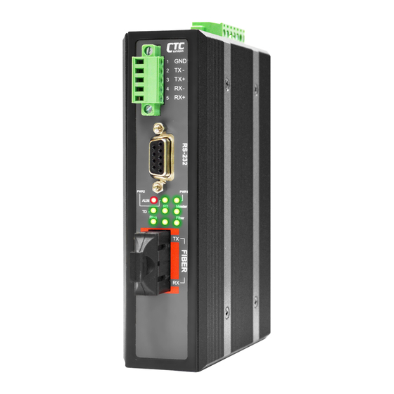
- Page 1 IFC-Serial, IFC-Serial-E Industrial Fiber Converter...
- Page 3 CTC Union Technologies makes no warranty, representation, or guarantee regarding the suitability of its products for any particular purpose, nor does CTC Union assume any liability arising out of the application or use of any product and specifically disclaims any and all liability, including without limitation any consequential or incidental damages.
- Page 4 IFC-Serial IFC-Serial-E This document is the current official release manual. Please check CTC Union's website for any updated manual or contact us by E-mail at sales@ctcu.com. Please address any comments for improving this manual or to point out omissions or errors to marketing@ctcu.com. Thank you.
-
Page 5: Table Of Contents
Table of Contents CHAPTER 1. INTRODUCTION ............................ 7 1.1 W .................................. 7 ELCOME 1.2 P ............................. 7 RODUCT ESCRIPTION 1.2.1 Features ................................7 1.2.2 Specifications ..............................7 1.2.3 Block Diagram ..............................8 1.2.4 Theory of Operation ............................9 1.2.5 Applications ............................... 9 1.2.6 RS-485 4 wire vs. - Page 6 Table of Contents This page left blank intentionally...
-
Page 7: Chapter 1 Introduction
Chapter 1. Introduction 1.1 Welcome Thank you for purchasing our IFC-SERIAL fiber port serial media converter. This media converter is an "industrial strength" product that employs rugged mechanical materials and construction, component selection for wide temperature, highly reliable and long life operation and an electrical design that prevents internal damage or data disruption from surges, power spikes or other electromagnetic interference. -
Page 8: Block Diagram
MTBF : 797,101 Hrs 1.2.3 Block Diagram The IFC-SERIAL has a configurable 2-wire / 4-wire RS-485/422 interface and two RS-232 3-wire interfaces. The two RS-232 interfaces share a common ground but are isolated from power ground and from the RS-485/422 interface by 2.5KV isolation. -
Page 9: Theory Of Operation
Chapter 1 Introduction 1.2.4 Theory of Operation The IFC-SERIAL uses control logic to connect an RS-485/422 interface, two RS-232 3-wire interfaces to a single bi- directional optical fiber channel. IFC-SERIAL units are interconnected by the fiber port in point-to-point applications. -
Page 10: Rs-485 Pull High, Pull Low
A terminating resistor is simply a resistor placed at the extreme end or ends of a cable. The value of the terminating resistor is ideally the same value as the characteristic impedance of the cable. In the IFC-SERIAL, this value is fixed at 120Ω. -
Page 11: Chapter 2 Installation
2.1.1 Bracket Mounting To support DIN Rail mounting, the IFC-SERIAL must first have the DIN Rail bracket installed. Position the bracket, as shown below, and use the provided flathead screws to attach the bracket to the center three mounting holes. -
Page 12: Rail Dismounting
Chapter 2 Installation 2.1.3 Rail Dismounting To remove the IFC-SERIAL unit, use a slight downward pressure [1] and release the lower rail from the IFC- SERIAL's bracket. Swing the unit out [2] and lift off and away from the DIN rail. -
Page 13: Electrical Installation
2.3.2 Alarm Contact The IFC-SERIAL has a single, normally open / normally closed alarm relay contact. Depending on some DIP switch settings, this alarm contact can create a closed or open circuit when conditions such as power failure or fiber disconnect occurs. -
Page 14: Rs-485/422 Connections
2.6 Fiber Connection The IFC-SERIAL is available with fiber connectors for SC or ST and for multi-mode or single mode fiber. The fiber connection require duplex cables and proper adherence to connections for RX and TX. The following table describes the attributes of the various transceivers available for the IFC-SERIAL. -
Page 15: Chapter 3. Configuration And Operation
120Ω Switch 1 : When connecting the IFC-SERIAL to only a single power source, leave this switch OFF or the alarm will be constantly on. When connecting to two separate power sources, turn this switch ON and alarm will occur if either power source fails. -
Page 16: Pull High/Low
3.1.3 LED Definitions The front panel has a 3 x 3 matrix of 2.5mm LEDs. The LEDs are used to quickly diagnose the link and alarm condition of the IFC-SERIAL. The following table lists and describes the meanings of the LEDs. -
Page 17: Operation
3.2.1 Two Unit Point-to-Point In the very simplest application, a duplex fiber connects two IFC-SERIAL units. One unit is set as 'Master' the other as 'Slave'. The RS-485 and RS-232 are completely isolated electrically. A receive signal can only be connected to either the RS-485 (terminal block) or to the RS-232 DB9 (not both at the same time). -
Page 18: Three Or More Units Ring Topology
Then its fiber transmit again connects to the next device fiber receive, until a completed ring is formed. The IFC-Serial operates completely at Layer 1. However, the logic control will ensure that any transmitted data will flow to each device in the ring but will not loop. The protocol layer is required to handle proper communication flow control.
Need help?
Do you have a question about the IFC-Serial and is the answer not in the manual?
Questions and answers