Advertisement
Product overview
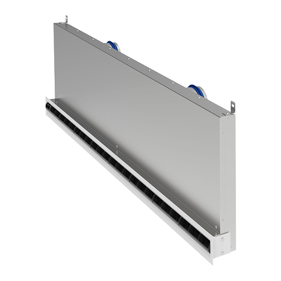
Fig. 1: Schematic illustration, CFS-50 shown
1
Front rail
2
Adjustable air control element
3
End angle
4
Plenum box
5
Cross-talk attenuator
Assembly instructions
Air diffusers
Wall diffuser
Air diffusers Wall diffuser
GB/en
6
Suspension lug
7
Spigot
8
Lip seal
9
Damper screen for volume flow rate balancing
TROX GmbH
Heinrich-Trox-Platz
47504 Neukirchen-Vluyn
Germany
Phone: +49 (0) 2845 202-0
Fax: +49 (0) 2845 202-265
E-mail: trox-de@troxgroup.com
http://www.troxtechnik.com
1
Advertisement
Table of Contents

Related Manuals for Trox Technik CFS-18


Summary of Contents for Trox Technik CFS-18
- Page 1 Assembly instructions GB/en TROX GmbH Heinrich-Trox-Platz 47504 Neukirchen-Vluyn Germany Phone: +49 (0) 2845 202-0 Air diffusers Fax: +49 (0) 2845 202-265 E-mail: trox-de@troxgroup.com http://www.troxtechnik.com Wall diffuser Product overview Fig. 1: Schematic illustration, CFS-50 shown Front rail Suspension lug Adjustable air control element Spigot End angle Lip seal...
-
Page 2: Important Notes
Important notes Important notes Air diffusers are used to supply cooled or heated air to rooms (within the specified supply air temper- Information on the installation manual ature differences). This manual enables operating or service personnel Depending on the area of application, special to correctly install the product described below and hygiene requirements must be observed during to use it safely and efficiently. -
Page 3: Transport And Storage
Transport and storage Protective gloves protect hands from friction, abra- Transport on site sions, punctures, deep cuts, and direct contact with hot surfaces. CAUTION! Safety shoes Danger of injury from sharp edges, sharp cor- ners and thin sheet metal parts! Sharp edges, sharp corners and thin sheet metal parts may cause cuts or grazes. - Page 4 Assembly Assembly Installation in lightweight partition walls General installation information Installation in lightweight partition walls Installation note: For room heights up to 4 m (lower edge of ceiling) Wall installation in lightweight partition wall After installation, all devices must be easily ...
- Page 5 Assembly Installation of slot diffuser for lightweight walls Installing the slot diffuser Personnel: Trained personnel Protective equipment: Industrial safety helmet Protective gloves Safety shoes Wall installation in light partition wall. Construction lengths suitable for the common distances of the metal stud frame, some changes might be required for the CW sections.
- Page 6 Assembly For larger dimensions, we recommend that two people carry out the assembly. Mounting on C-profile. Fig. 4: The plenum box must be acoustically decou- pled on site Air diffusers Wall diffuser...
- Page 7 Assembly Fig. 5: Installation in lightweight partition wall Ceiling slab Suspended ceiling Slot diffuser for wall installation Air duct Front rail Fig. 6: Fitting the seal The unit is inserted into the drywall with protective foil. Sound insulation between C-profile and wall slot diffuser. The wall is completed with panels etc.
- Page 8 Assembly Installation of front rail The protective film must be removed before the front rail can be fitted. Care must be taken to ensure that no further soiling is caused by construction activities. Assemble the loose fixing material as shown. ...
-
Page 9: Technical Data
Technical data Technical data Dimensions and weights Fig. 7: CFS variant with 1 spigot Fig. 8: CFS variant with 2 spigots Air diffusers Wall diffuser... - Page 10 Technical data Fig. 9: Installation opening in lightweight walls CFS-18 No. of spigots 1/2* 1000 1000 1022 1/2* 1100 1100 1095 1122 1/2* 1200 1200 1195 1222 1/2* * System SE: always with 2 spigots CFS-35/50 No. of spigots 1/2*...
- Page 11 Technical data Weights CFS-18 1 slot 2 slot Plenum box Plenum box Diffuser Diffuser face face =290 =340 =440 =290 =340 =440 1000 1100 1200 Total weight = weight of diffuser face + weight of plenum box Weights CFS-35 1 slot...
-
Page 12: Setting The Air Discharge Direction
Setting the air discharge direction Variant Front rail 18-1 Front rail 18-2 Front rail 35-1 Front rail 35-2 Front rail 35-3 Front rail 50-1 Front rail 50-2 Setting the air discharge direction These are only schematic diagrams to illustrate the setting of the air control elements. The air control blades have notches on the mullions that are used for adjustment. - Page 13 Setting the air discharge direction Volume flow rate balancing Fig. 12: Volume flow rate balancing CFS-35/50 Fig. 10: Volume flow rate balancing CFS-18 Adjusted by moving the lever (closed position shown) Adjusted with cords (closed position shown) Green = CLOSE White = OPEN Fig.
-
Page 14: Product Details
Product details Product details Factory settings Fig. 17: Suspension lug turned sideways For ceiling installation Fig. 14: Factory settings Fig. 15: Hanging bracket set up and rotated For wall mounting Fig. 16: Suspension bracket set up and rotated For suspending from the ceiling Air diffusers Wall diffuser... -
Page 15: Maintenance
Maintenance Maintenance Disposal System owner's responsibility ENVIRONMENT! WARNING! Risk of harm to the environment due to incor- rect disposal! Only authorised specialist personnel are Incorrect disposal can harm the environment. allowed to perform the described mainte- nance measures. – Be sure to comply with the relevant national guidelines and regulations.
Need help?
Do you have a question about the CFS-18 and is the answer not in the manual?
Questions and answers