
Subscribe to Our Youtube Channel
Related Manuals for Trox Technik PWX Series


Summary of Contents for Trox Technik PWX Series
- Page 1 Installation & Operating Manual GB/en Waterside Fancoil Units Type PWX Read the instructions prior to performing any task (11/2022) Waterside Fancoil Units – Type PWX...
- Page 2 TROX UK Ltd Caxton Way Thetford, Norfolk IP24 3SQ Phone: +44 (0) 1842 754545 Fax: +44 (0) 1842 763051 E-mail: sales@troxuk.co.uk Internet: http://www.troxuk.co.uk © TROX UK Ltd 12/2022 125979T – 11/2022 Original Instructions Waterside Fancoil Units – Type PWX (12/2022)
- Page 3 General Information General information Contact details About this manual Online www.troxuk.co.uk This operating and installation manual enables operating or service Phone +44 (0) 1842 754545 personnel to correctly install the waterside fancoil unit and to use it safely and efficiently. This operating and installation manual is intended for use by fitting Copyright and installation companies, in-house technicians, technical staff,...
-
Page 4: Table Of Contents
Table of Contents Contents PWX unit overview ............5 Safety ................6 Symbols used in this manual ......... 6 Equipment use ..............6 Safety signs ..............7 Residual risks ..............7 Qualified staff ..............8 Personal protective equipment........8 Behaviour in the event of accidents ......9 Transport and storage ............ -
Page 5: Pwx Unit Overview
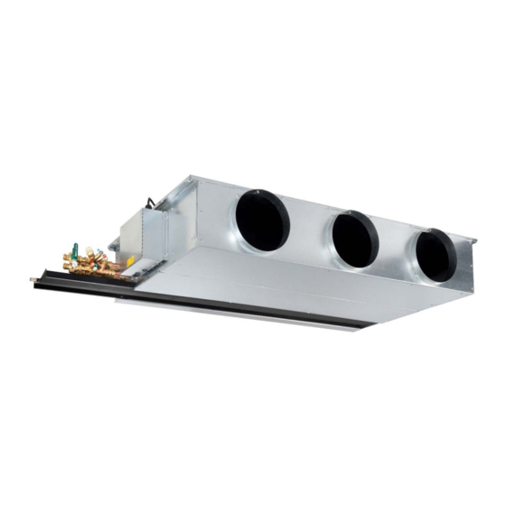
PWX unit overview PWX unit overview Fig 1: Waterside fancoil unit ① ⑥ ② ⑦ Condensate drip tray Motor ③ ⑧ Heat exchanger Spigot ④ ⑨ Fan access panel Inlet air filter ⑤ ⑩ Fan deck Controls enclosure (base) Controls enclosure access panel (12/2022) Waterside Fancoil Units –... -
Page 6: Safety
Safety Safety Additional markers In order to highlight instructions, results, lists, references and other elements, the following markers are used in this manual: Symbols used in this manual Marker Explanation Safety notes Symbols are used in this manual to alert readers to areas of potential ▶... -
Page 7: Safety Signs
Safety Operation in rooms where the supply or extract air contains 2.4.2 Dirt and objects lying around particles that are conductive, aggressive corrosive, combustible or hazardous to health. CAUTION! Operation in rooms where the humidity is permanently high (>... -
Page 8: Qualified Staff
Safety 2.4.6 Unsuitable installation location HVAC technicians are individuals who have sufficient professional or technical training, knowledge and actual experience to enable them to work on HVAC systems, understand any potential hazards related WARNING! to the work under consideration, and recognise and avoid any risks involved. -
Page 9: Behaviour In The Event Of Accidents
Safety / Transport and storage Safety shoes 3.1.2 Symbols on the packaging The packaging carries the following marks and symbols. Be sure to Safety shoes protect the feet from crushing, follow them when you are moving the unit. falling parts and prevent slipping on a slippery floor. -
Page 10: Moving Packages
Transport and storage / Installation Moving packages Damage to good being moved 3.3.1 Safety notes regarding transport Unloading Risk of damage to property due to the incorrect handling or Improper transport equipment lifting of units! Units will be delivered on wooden pallets suitable for use with; If you handle or move packages incorrectly, they may topple or fall. -
Page 11: Installation
Transport and storage / Installation Storage Area Installation Please note: The area is internal and will not be affected by the weather. Personnel: The surface where the equipment is to be placed is flat. HVAC technician The equipment will be raised from the floor to allow airflow and ... -
Page 12: General Installation Information
Installation General installation information The fancoil unit and attachments are to be installed and fixed to the building structure, horizontally. Suspension components for installing the fancoil unit are not included in the supply package, but have to be selected by others and fit for the project specific installation. 4.1.1 Before installation Before you install the unit, the following should be checked;... -
Page 13: Installing Fancoil Attachments
Installation Installing fancoil attachments Unit size / Fixing Centres ‘B’ Weight (dry) designation [mm] [kg] 4.3.1 Inlet Plenum (IP) PWX-60 PWX-90 PWX-120 1234 PWX-150 1534 PWX-180 1834 PWX-205 2084 Inlet plenums can be used to provide a sealed connection to the Weights exclude valve assemblies or free-issue equipment fancoil from return air diffusers or to connect fresh air from the AHU. - Page 14 Installation 4.3.4 Attachment weights and fixing centres Unit size / ‘W’ Weight [kg] designation [mm] IA/DA 1200 1500 1800 2050 4.3.5 Attachment installation Tolerance ±1.0mm PWX attachment fixings 4.3.3 Discharge Attenuator (DAR) If the fancoil unit was not supplied with fixings, these must be sourced (by others) before installation can be completed.
-
Page 15: Connecting The Water Pipes
Installation Taking precautions to protect the fancoil (remove inlet filter Drain valves and vent valves are required; if they are not part of the supply package, they have to be provided by others. if necessary), drill each point (3 per side) with hole size to Using the correct brackets, install the pipework up to the FCU with suit M6 rivnut and install M6 rivnuts. -
Page 16: Connecting The Ductwork
Installation ▶ Check the system for leaks immediately after filling and Interfaces Dimensions Connection options then at regular intervals. Heat Exchanger Ø15mm or Compression coupling ▶ Backflush the heat exchanger, avoiding flushing through CHW/LTHW Ø22mm plain (rigid) the valve sets, until the water is clear. Refer to local connection copper tails Capillary solder (rigid) - Page 17 Installation Install the spiral galvanized ducting, or rectangular if needed, Unit size / Rectangular Spigot Max. Circular Spigot connecting to the fancoil unit out to the location of the supply designation length ‘R’ ATD’s. [mm] Where the use of acoustic flexible connections between the ...
-
Page 18: Making Electrical Connections
Installation / Making electrical connections ▶ Place the new spigot into the opening, aligning the tabs Making electrical connections with the holes within the fancoil casing. The short end of the spigot should be inserted into the fancoil Personnel: Skilled qualified electrician ... -
Page 19: Wiring
Installation / Initial Commissioning Wiring TROX PWX fancoil units, equipped with an integral electric heater, include Kanthal D (or equivalent) element, magnesium oxide insulation contained within 304 grade stainless steel tube and ▶ Take off the control enclosure lid; to do so, loosen the M5 stainless-steel helical fin surround. -
Page 20: Initial Commissioning
Initial Commissioning Initial commissioning Pipework is connected correctly (flow, return, heating, cooling etc.) and does not put stress on the fancoil connections or create vibrations. Personnel: The mains water system has been hydraulically balanced. Skilled qualified electrician Pipework is insulated, vapor sealed and labelled. -
Page 21: Post Start-Up Checks
Initial Commissioning / Maintenance ▶ Once the fans have run for 10 minutes, FCU volume flow Maintenance and cleaning rate and external static pressure should be checked against design values. Refer to TROX technical schedule Personnel: for confirmation of design flow rate and external pressure. Skilled qualified electrician ... - Page 22 Maintenance Maintenance 7.1.2 Inspecting and replacing the fans Any components removed from the fancoil unit during inspection and DANGER! maintenance should be stored away securely, at low level. Ensure all components are reinstalled in the correct orientation and to the same Danger of electric shock! Do not touch any live components! unit with fixings securely tightened.
- Page 23 Maintenance 7.1.2.1 Removing fan access panel 7.1.2.2 Inspecting the fans To allow inspection of the fan assemblies, the fan access panel must Regular inspection of the fan assemblies within each fancoil should be undertaken as part of the building Planned preventative be removed as follows;...
- Page 24 Maintenance Type PWX fancoil units are supplied with either individual fan/motor ▶ Remove the fan assembly through the access opening taking care not to damage any of the surrounding insulation assemblies (...-F7) or common shaft fan assemblies (...-F10). Both material, sealing gaskets or internal wiring. fan types can be removed and/or replaced using the procedure below;...
- Page 25 Maintenance 7.1.3 Cleaning the heat exchanger 7.1.3.1 Replacing the heat exchanger CAUTION! CAUTION! Danger of injury from sharp edges, sharp corners and thin Danger of injury from sharp edges, sharp corners and thin sheet metal parts! sheet metal parts! Sharp edges, sharp corners and thin sheet metal parts may cause Sharp edges, sharp corners and thin sheet metal parts may cause cuts or grazes.
- Page 26 Maintenance ▶ Gently lower the drip tray away from the FCU and store safely for re-installation. ▶ To remove the heat exchanger, provide support along the full length. Identify and remove all fixings used to secure the heat exchanger to the FCU casework (x4 each side) ▶...
-
Page 27: Replacement Parts List
Replacement Parts Replacement parts list Ordering replacement parts You can identify order-specific components of the fancoil unit either by a code on the component itself or by the FCU reference number detailed on the label or TROX technical schedule. Name Replacement part No. -
Page 28: Appendix A Declaration Of Incorporation / Conformity
Appendix A Appendix A Declaration of Incorporation / Conformity UKCA Declaration of Incorporation Waterside Fancoil Units – Type PWX (12/2022) - Page 29 Appendix A UKCA Declaration of Conformity (12/2022) Waterside Fancoil Units – Type PWX...
-
Page 30: Appendix B Commissioning / Maintenance Report
Appendix B Appendix B Commissioning / Maintenance Report Building Name: Floor: Unit Ref: Date: □ □ Commissioning Maintenance Interval [months] Complete Item to be checked Measures Cleaning / replacing inlet filters Remove dust and contamination from the inlet filter and □... -
Page 31: Appendix C Initial Start-Up
Appendix C Before powering up the fan coil unit, it is necessary to; Appendix C Initial Start-Up Connect valve actuator(s) to valve bodies in accordance with Initial start-up and addressing valve installation instructions. Chapter 4.4 ‘Connecting the water pipes’. Personnel: Skilled qualified electrician If there is a condensate pump, the pump cables should not be... - Page 32 Appendix C ▶ Use the top left button to navigate to ‘8 Setup menu’ then ▶ Use the bottom left button to navigate to ‘2 Return to press the bottom right button. Previous’ then press the bottom right button. Navigate Press Navigate Press...
- Page 33 Appendix C Enter Fan & Mode Settings to adjust the fan volume ▶ Use the bottom left button to navigate to ’17 Fan Max. Auto H’ then use the right-hand buttons to set the (Fan ▶ From the Setup Menu, use the top left button to navigate to Max) previously noted voltage.
-
Page 34: C1.3 Control Type 2 (Standalone)
Appendix C C1.3 Control Type 2 (Standalone) WIRING NOTE: 1x 0.5...1.5mm² (16 gauge). Max cable length 80m. Should any of the controller parameters require modification to Each RDG-160T controller is delivered with FCU specific facilitate future adaptations, please contact TROX UK for guidance. configuration preloaded within each controller. -
Page 35: Appendix D Order Code
Appendix D Appendix D Order Code (12/2022) Waterside Fancoil Units – Type PWX... - Page 36 TROX UK Ltd Phone: +44 (0) 1842 754545 Caxton Way Fax: +44 (0) 1842 763051 Thetford, Norfolk E-mail: trox@troxuk.co.uk Waterside Fancoil Units – Type PWX (12/2022) IP24 3SQ Internet: http://www.troxuk.co.uk © TROX UK Ltd 2022...
Need help?
Do you have a question about the PWX Series and is the answer not in the manual?
Questions and answers