
Related Manuals for Trox Technik FKA2-EU


Summary of Contents for Trox Technik FKA2-EU
- Page 1 Installation and operating manual GB/en Fire damper Type FKA2-EU according to Declaration of Performance DoP / FKA2-EU / DE / 001 Read the instructions prior to performing any task!
- Page 2 TROX GmbH Heinrich-Trox-Platz 47504 Neukirchen-Vluyn Germany Phone: +49 (0) 2845 2020 Fax: +49 (0) 2845 202-265 E-mail: trox@trox.de Internet: http://www.troxtechnik.com Translation of the original A00000076523, 1, GB/en 09/2019 © 2019 Fire damper Type FKA2-EU...
- Page 3 To ensure that your request is processed as quickly as possible, please keep the following information ready: Product name TROX order number Delivery date Brief description of the fault Online www.troxtechnik.com Phone +49 2845 202-400 Fire damper Type FKA2-EU...
- Page 4 Warning – danger zone. NOTICE! Potentially hazardous situation which, if not avoided, may result in property damage. ENVIRONMENT! Environmental pollution hazard. Tips and recommendations Useful tips and recommendations as well as informa- tion for efficient and fault-free operation. Fire damper Type FKA2-EU...
-
Page 5: Table Of Contents
ES..........82 2.2 FKA2-EU with fusible link......8 5.8.3 Dry mortarless installation with fire batt.. 83 2.3 FKA2-EU with spring return actuator..11 5.9 Shaft walls with metal support structure..84 2.4 FKA2-EU with spring return actuator and 5.9.1 Mortar-based installation...... -
Page 6: Safety
Additional provision: risks involved. For use in extract air systems in commercial kitchens as an air transfer damper, the following regulations must be observed. Fire damper Type FKA2-EU... -
Page 7: Technical Data
EN 1751 Ventilation for buildings – Air terminal devices Declaration of performance DoP / FKA2-EU / DE / 001 Temperatures may differ for units with attachments. Details for other applications are available on request. Data applies to uniform upstream and downstream conditions for the fire damper. -
Page 8: Fka2-Eu With Fusible Link
Length of the fire damper (casing length) Installation side 115 mm Operating side Keep clear to provide access for operation Weight of FKA2-EU with fusible link, see table Ä 9. Ä 9. Sizes 1 to 3, see table ... - Page 9 Technical data FKA2-EU with fusible link Limit switches Connecting cable length / cross section 1 m / 3 × 0.34 mm² Protection level IP 66 Type of contact 1 changeover, gold-plated Maximum switching current 0.5 A Maximum switching voltage 30 V DC, 250 V AC Contact resistance approx.
- Page 10 Technical data FKA2-EU with fusible link Flange holes Fig. 3: Flange holes L = 305 mm – uneven and even number of holes Fig. 4: Flange holes L = 500 mm – uneven and even number of holes A Installation side...
-
Page 11: Fka2-Eu With Spring Return Actuator
3 – BFN vertical Keep clear to provide access for operation Installation side Operating side Ä 9. Weight of FKA2-EU with fusible link + approx. 1 kg (BFL... and BFN...), see table Sizes 1 to 3, see table Ä 9. ... - Page 12 Technical data FKA2-EU with spring return actuator Spring return actuator BFL... Construction 230-T TR 24-T-ST TR Supply voltage 230 V AC, 50/60 Hz 24 V AC/DC, 50/60 Hz Functional range 198 – 264 V AC 19.2 – 28.8 V AC 21.6 –...
- Page 13 Technical data FKA2-EU with spring return actuator Spring return actuator BFN... Construction 230-T TR 24-T-ST TR Supply voltage 230 V AC, 50/60 Hz 24 V AC/DC, 50/60 Hz Functional range 198 – 264 V AC 19.2 – 28.8 V AC 21.6 –...
- Page 14 1 m, 2 × 0.75 mm² / 1 m, 6 × 0.75 mm² (free of halo- gens) BF actuator optional, weight of FKA2-EU with fusible link + approx. 2 kg ¹ Up to 75 °C the safe position will definitely be reached.
- Page 15 3 – GNA vertical Keep clear to provide access for operation Installation side Operating side Ä 9. Weight of FKA2-EU with fusible link + approx. 1.4 kg (GRA... and GNA...), see table Ä 9. Sizes 1 to 3, see table ...
- Page 16 Technical data FKA2-EU with spring return actuator Spring return actuator GRA... Construction 326.1E 126.1E Supply voltage 230 V AC, 50/60 Hz 24 V AC, 50/60 Hz / 24 – 48 V DC Functional range 198 – 264 V AC 19.2 – 28.8 V AC 19.2 –...
- Page 17 Connecting cable Actuator / limit switch 0.9 m, 6 × 0.75 mm² (free of halogens) GGA actuator optional, weight of FKA2-EU with fusible link + approx. 2.5 kg *Connecting cable at the bottom FKA2-EU with Joventa spring return actuator The FKA2-EU can also be supplied with Joventa spring return actuator on request: SFR 2.90 T...
-
Page 18: Fka2-Eu With Spring Return Actuator And Duct Smoke Detector
3 – BFN vertical Keep clear to provide access for operation Installation side Operating side Weight of FKA2-EU with fusible link + approx. 2.5 kg (BFL... and BFN...), see table Ä 9. Ä 12 and Ä 14 Technical data for spring return actuator, see table ... -
Page 19: Transport And Storage
Do not expose the unit to the effects of weather (not even in its packaging). Do not store the unit below -40 °C or above 50 °C. Packaging Properly dispose of packaging material. Fire damper Type FKA2-EU... -
Page 20: Parts And Function
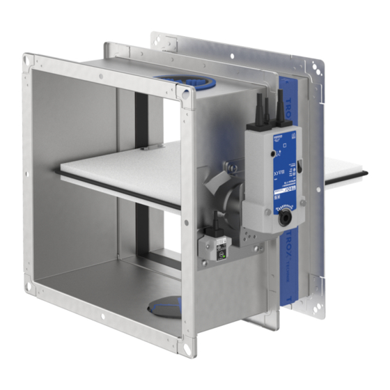
( 95 °C in warm air ventilation systems). If the damper blade closes due to a temperature increase (i.e. in the event of a fire), it must not be reopened. 4.1 FKA2-EU with fusible link Fig. 9: FKA2-EU with spring return actuator Casing (galvanised) Damper blade Inspection access 10.1... -
Page 21: Fka2-Eu With Spring Return Actuator And Duct Smoke Detector
Parts and function FKA2-EU with spring return actuator and duct smoke detector 4.3 FKA2-EU with spring return actuator and duct smoke detector Fig. 10: FKA2-EU with spring return actuator and duct smoke detector Casing (galvanised) Damper blade Inspection access 10.1 Spring return actuator 10.12 Duct smoke detector RM-O-3-D (fixed with... -
Page 22: Installation
Ä 76 EI 30 S – Thickness increased near the installation opening N = Mortar-based installation E = Installation kit An extension piece may be required W = Fire batt dependent on size only horizontal installation position Fire damper Type FKA2-EU... - Page 23 N = Mortar-based installation Thickness increased near the installation opening E = Installation kit An extension piece may be required W = Fire batt dependent on size only horizontal installation position Fire damper Type FKA2-EU...
-
Page 24: Safety Notes Regarding Installation
≥40 mm distance to load-bearing structural ele- ments unless stated otherwise for a particular instal- lation situation. When installing the FKA2-EU, the statics of the sup- port structure (wall / ceiling) must be ensured by others, even in the event of a fire. - Page 25 Up to EI 120 S Installation side Operating side Note: The installation situation shown is representative of all support structures. Fig. 13: Horizontal installation Fire damper Type FKA2-EU...
- Page 26 A, B, D – F E, F E, F Solid wood wall / cross-laminated timber wall E, F E, F E, F Solid ceiling slab A, B, D – F E, F Wooden beam ceiling E, F Fire damper Type FKA2-EU...
- Page 27 We recom- mend a gap of at least 20 mm (note the minimum installation opening size). Reinforcement should meet structural requirements. Fig. 16: FKA2-EU with prop FKA2-EU 9.3 Prop Installation side Operating side Fig.
- Page 28 The holes must be pre-drilled to Æ 4 mm. Fig. 17: Installation kit – free space (with normal installa- tion) FKA2-EU Installation kit ES Wall Dry wall screw, to be provided by others 5.15 Bracket Fire damper Type FKA2-EU...
- Page 29 Dry wall screw, to be provided by others 5.15 Bracket Fig. 20: Fire-resistant sealant FKA2-EU Fire batt with ablative coating 8.21 Fire-resistant sealant Installation side Fig. 19: Fastening the installation kit to the stud frame Operating side FKA2-EU Fire damper Type FKA2-EU...
- Page 30 Ablative coating Würth Ablationsbeschichtung I Requirements for wall and ceiling systems ('Ablation coating I') FKA2-EU fire dampers may be installed in wall and ceiling systems if these walls and ceilings have been erected in compliance with the relevant regulations and Ablative coating ...
- Page 31 Additional layers of cladding (if stated in the usability certificate for the wall) and double stud construc- Fig. 22: Distance from the FKA2-EU to other TROX fire tions are approved. dampers in mortar-based installation Connect the metal sections near the installation ...
- Page 32 If necessary, provide trim panels and screw-fix them to the support structure Ensure accessibility to the shaft from the rear. Installation is carried out with the actuator on the outside of the shaft. Fire damper Type FKA2-EU...
-
Page 33: Installation Kit Supply Package And Assembly Es
Fig. 24: Assembly of installation kit ES for dry mortarless installation Installation kit ES 5.19 Connecting clip (8 pieces) B part (2 ×) 2.9.1 6.12 Intumescent seal (4 pieces) H part (2 ×) 2.9.2 Fire damper Type FKA2-EU... - Page 34 Installation kit remote from walls For installation remote from walls and ceilings, the intumescent seal (6.12) on the installation kit ES must be removed from the perimeter by others. The sealing tape (6.21) may not be affixed. Fire damper Type FKA2-EU...
-
Page 35: Solid Walls
Mortar-based installation B + 450 max. H + 450 max. 60 – 225 ≤ 600 Dry mortarless installation H + 1200 max. H + 1200 max. with fire batt Observe maximum permitted size of the fire batt! Fire damper Type FKA2-EU... -
Page 36: Mortar-Based Installation
Fig. 28: Mortar-based installation into a solid wall, flange to flange, illustration shows side by side installation (applies also to installation of dampers on top of each other) FKA2-EU Up to EI 120 S Mortar Installation side Solid wall Operating side Fire damper Type FKA2-EU... - Page 37 Installation Solid walls > Mortar-based installation Fig. 29: Mortar-based installation into a solid wall, combined, FKA2-EU und FKRS-EU FKA2-EU up to B × H = 800 × 400 mm Up to EI 90 S FKRS-EU Installation side Mortar Operating side...
-
Page 38: Mortar-Based Installation With Partial Mortaring
Distance between two FKA2-EU in one installation opening 60 – 225 mm The difficult-to-access installation gap between the FKA2-EU and the wall / ceiling must be completely filled with mineral wool between the wall flanges. Completely close off the remaining gaps (on 2 or 3 sides) with mortar. -
Page 39: Dry Mortarless Installation With Installation Kit Es
B × H > 800 × 400 mm plus 6.1) Note: * Remove intumescent seal (6.12) and seal (6.21) or do not affix, see Ä 33. Further installation details and components to be provided by the customer on request. Fire damper Type FKA2-EU... - Page 40 Solid walls > Dry mortarless installation with installation kit ES Fig. 32: Dry mortarless installation with installation kit ES, remote from a solid wall (wall penetration) FKA2-EU FKA2-EU suspension system (by others), con- Installation kit ES * sisting of: Solid wall, wall penetration according to Promat®...
- Page 41 Promat® manual, construction 478, latest edition (from B × H > 800 × 400 mm plus 6.1) FKA2-EU suspension system (by others), con- sisting of: Threaded rod M12 Note: * Remove intumescent seal (6.12) and seal (6.21) or do not affix, see Ä...
- Page 42 ≥ 155 mm distance to the wall or ceiling slab ≥ 310 mm distance between two fire dampers Enough clear space is required to attach the installation kit to the fire damper. Ä 91. Note: Fire damper and duct must be suspended Fire damper Type FKA2-EU...
-
Page 43: Dry Mortarless Installation With Fire Batt
Ä 29 f Fire batt distances / dimensions, see Suspension Ä 92 Casing length L = 305 or 500 mm ≥ 200 mm distance between two fire dampers in separate installation openings Fire damper Type FKA2-EU... -
Page 44: Solid Ceiling Slabs
Additional requirements: solid ceiling slabs Ä 31 Solid wall Ä 26 Distances and installation orientations, see Installation type Installation opening [mm] Distance [mm] ≤ 225 Mortar-based installation B + 450 max. H + 450 max. 60 – 225 Fire damper Type FKA2-EU... -
Page 45: Mortar-Based Installation Into Solid Ceiling Slabs
Solid ceiling slabs > Mortar-based installation into solid ceiling slabs 5.5.1 Mortar-based installation into solid ceiling slabs Fig. 36: Mortar-based installation into a solid ceiling slab, suspended or upright FKA2-EU – Up to EI 120 S Mortar Installation side Solid ceiling slab Operating side Fire damper Type FKA2-EU... - Page 46 Fig. 37: Mortar-based installation into a solid ceiling slab with screed and footfall sound insulation, suspended or upright FKA2-EU 6.23 Football sound insulation Mortar – Up to EI 120 S Reinforced concrete Installation side Solid ceiling slab Operating side 6.22 Screed Fire damper Type FKA2-EU...
- Page 47 FKA2-EU Up to EI 120 S Mortar Installation side Solid ceiling slab Operating side Additional requirements: mortar-based installation in solid ceiling slabs Solid wall Ä 31 Casing length L = 305 or 500 mm Fire damper Type FKA2-EU...
-
Page 48: Mortar-Based Installation Into A Concrete Base
Tightly seal any openings in the old fire damper casing with a sheet metal plate. Create a concrete base according to Fig. 39 or equivalent. Fire damper Type FKA2-EU... -
Page 49: Mortar-Based Installation In Conjunction With Wooden Beam Ceilings
Create a partial concrete ceiling around the fire damper, ≥ 100 mm, ≥ 125 mm thick. Structural and fire resistance properties of the ceiling construction, including the attachment to the concrete, have to be evaluated and ensured by others. Fire damper Type FKA2-EU... -
Page 50: Mortar-Based Installation In Conjunction With Solid Wood Ceilings
Create a partial concrete ceiling around the fire damper, ≥ 100 mm, ≥ 125 mm thick. Structural and fire resistance properties of the ceiling construction, including the attachment to the concrete, have to be evaluated and ensured by others. Fire damper Type FKA2-EU... -
Page 51: Dry Mortarless Installation With Installation Kit Es
Installation Solid ceiling slabs > Dry mortarless installation with installation kit ES 5.5.5 Dry mortarless installation with installation kit ES Fig. 42: Dry mortarless installation remote from solid ceiling slabs Fire damper Type FKA2-EU... - Page 52 (Promat® manual). Attach the suspensions according to the manufacturer's instructions (Promat® manual) Ä 91. Attachment to the ceiling, detail Z Fig. 42. Seal the perimeter gap between the duct and the ceiling with mortar. Fire damper Type FKA2-EU...
-
Page 53: Lightweight Partition Walls And Compart- Ment Walls With Metal Support Structure
Lightweight partition walls and compartment walls with metal support structure 5.6 Lightweight partition walls and compartment walls with metal support struc- ture Fig. 43: Lightweight partition wall with metal support structure and cladding on both sides Fire damper Type FKA2-EU... - Page 54 (without trim panels: B2 = B1, H2 = H1) Mineral wool depending on wall construction Closed side of metal section must face the UW section installation opening 7.1a UW section, cut in and bent or cut off Arrangement variable Fire damper Type FKA2-EU...
- Page 55 Fig. 45: Metal support structure of compartment wall, single and double stud system Dry wall screw UW section Hexagon head screw M6 CW section Carriage bolt, L ≤ 50 mm, with nut and washer UA section Steel rivet Installation opening according to installation 5.14 Angle bracket details Fire damper Type FKA2-EU...
- Page 56 UW sections, cut to size by others, overlapping Mortar Installation side Lightweight partition wall with metal support struc- Operating side ture or steel support structure, cladding on both sides Dry wall screw, with a distance of ≤ 100 mm Fire damper Type FKA2-EU...
-
Page 57: Mortar-Based Installation
Solid ceiling slab / solid floor Installation near the floor analogous to Mineral wool depending on wall construction – Up to EI 120 S 6.11 Insulating strip (depending on wall construction) Installation side 7.10 Trim panels Operating side Fire damper Type FKA2-EU... - Page 58 Mineral wool depending on wall construction Up to EI 120 S 6.11 Insulating strip (depending on wall construction) Installation side 7.10 Trim panels Operating side 7.13 Cladding 7.14 Reinforcing board of the same material as the wall Fire damper Type FKA2-EU...
- Page 59 Optional, according to installation details Fig. 47 Lightweight partition wall with metal support and Fig. 48 structure, cladding on both sides Up to EI 120 S Mineral wool depending on wall construction Installation side 7.10 Trim panels Operating side Fire damper Type FKA2-EU...
- Page 60 Installation Lightweight partition walls and compartment walls with metal support structure > Mortar-based installation Fig. 50: Mortar-based installation into a lightweight partition wall, FKA2-EU and FKRS-EU combined FKA2-EU up to B × H = 800 × 400 mm 7.13 Cladding FKRS-EU Optional, according to installation details Fig.
- Page 61 Lightweight partition wall or compartment wall, see Ä 31 Casing lengths L = 305 and 500 mm EI 120 S: distance between two FKA2-EU 60 – 225 mm fire dampers of the same size in one installation opening. Fire damper Type FKA2-EU...
-
Page 62: Dry Mortarless Installation With Installation Kit Es
B × H = 200 × 100 – 1500 × 800 mm floor) Mineral wool, ≥ 1000 °C, ≥ 80 kg/m³ Installation side Mineral wool depending on wall construction Operating side 6.11 Insulating strip (depending on wall construction) 7.10 Trim panels Fire damper Type FKA2-EU... - Page 63 Up to EI 90 S: B × H = 200 × 100 – 1500 × 800 mm 7.13 Cladding 7.14 Reinforcing board of the same material (required Installation side for wall thicknesses > 100 mm) Operating side Fire damper Type FKA2-EU...
- Page 64 B × H > 800 × 400 – 1500 × 800 mm 7.10 Trim panels 7.13 Cladding Up to EI 90 S: B × H = 200 × 100 – 1500 × 800 mm Installation side Operating side Fire damper Type FKA2-EU...
- Page 65 Ensure accessibility from the rear. Ä 33. Mount the installation kit onto the fire damper, see Attach the fire damper with brackets and dry wall screws to the metal support structure, see Fig. 52 and Ä 33. Fire damper Type FKA2-EU...
-
Page 66: Dry Mortarless Installation With Installa- Tion Kit Es Remote From A Lightweight Partition Wall
5.6.3 Dry mortarless installation with installation kit ES remote from a lightweight parti- tion wall Fig. 56: Dry mortarless installation with installation kit ES remote from a lightweight partition wall FKA2-EU FKA2-EU suspension system (by others), con- Installation kit ES * sisting of: Lightweight partition wall with metal support Threaded rod M12 Hilti mounting rail MQ 41 ×... - Page 67 ≥ 100 mm distance to the wall or ceiling slab ≥ 350 mm distance between two fire dampers Enough clear space is required to attach the installation kit to the fire damper. Ä 91. Note: Fire damper and duct must be suspended Fire damper Type FKA2-EU...
-
Page 68: Dry Mortarless Installation With Fire Batt
B × H = 200 × 100 – 1500 × 800 mm Mineral wool depending on wall construction 6.11 Insulating strip (depending on wall construction) Installation side 7.10 Trim panels, dual-layer with W > 100 mm Operating side Fire damper Type FKA2-EU... - Page 69 Up to EI 60 S Mineral wool depending on wall construction EI 30 S to EI 120 S 6.11 Insulating strip (depending on wall construction) Installation side 7.10 Trim panels, dual-layer with W > 100 mm Operating side 7.13 Cladding Fire damper Type FKA2-EU...
- Page 70 Ä 29 f Fire batt distances / dimensions, see Suspension Ä 92 Casing lengths L = 305 and 500 mm ≥ 200 mm distance between two fire dampers in separate installation openings Fire damper Type FKA2-EU...
-
Page 71: Lightweight Partition Walls With Timber Support Structure
60 × 80 mm Mineral wool, depending on wall construction Timber stud, at least 60 × 80 mm B1 × H1 Clear installation opening B2 × H2 7.11 Trim panels, double layer, staggered joints Opening in the half-timbered construction Fire damper Type FKA2-EU... - Page 72 Dry mortarless installation B + 140 H + 140 with installation kit ES Dry mortarless installation B + 80 to 1200 H + 80 to 1200 with fire batt Installation opening tolerance ± 2 mm Fire damper Type FKA2-EU...
-
Page 73: Mortar-Based Installation
EI 30 S 7.10 Trim panels (fire-resistant) EI 30 to EI 120 S Installation side 7.11 Trim panels, double layer, staggered joints 7.12 Trim panels, wood sheet, at least 600 kg/³ Operating side 7.13a Cladding, fire-resistant Fire damper Type FKA2-EU... - Page 74 ≥ 1000 °C, ≥ 50 kg/m³, or bricks, aerated con- EI 30 to EI 90 S crete, lightweight concrete, reinforced concrete Installation side or clay) Operating side Half-timbered construction 7.11 Trim panels, fire-resistant, double layer, stag- gered joints 7.13 Cladding Fire damper Type FKA2-EU...
- Page 75 Trim panels, fire-resistant, double layer, stag- gered joints Additional requirements: mortar-based installation in lightweight partition walls with timber studs Ä 32 Timber stud wall or half-timbered construction, Casing lengths L = 305 and 500 mm Fire damper Type FKA2-EU...
-
Page 76: Dry Mortarless Installation With Installation Kit Es
Trim panels (fire-resistant) 7.11 Trim panels, fire-resistant, double layer, stag- EI 30 S gered joints to EI 120 S (horizontal installation position) 7.12 Trim panels, wood sheet, at least 600 kg/³ Installation side 7.13a Cladding, fire-resistant Operating side Fire damper Type FKA2-EU... - Page 77 Ä 33. Mount the installation kit onto the fire damper, see Fix the fire damper with brackets and dry wall screws to the timber stud wall or half-timbered construction, see Ä 33. Fig. 65 and Fire damper Type FKA2-EU...
-
Page 78: Dry Mortarless Installation With Fire Batt
B × H = 200 × 100 – 1500 × 800 mm 7.11 Trim panels, fire-resistant, double layer, stag- gered joints EI 30 S 7.12 Trim panels, wood sheet, at least 600 kg/³ EI 30 to EI 120 S 7.13a Cladding, fire-resistant Installation side Operating side Fire damper Type FKA2-EU... - Page 79 Timber stud wall or half-timbered construction, Ä 32 Ä 29 f Fire batt distances / dimensions, see Casing lengths L = 305 and 500 mm ≥ 200 mm distance between two fire dampers in separate installation openings Fire damper Type FKA2-EU...
-
Page 80: Solid Wood Walls
Dry mortarless installation B + 140 H + 140 with installation kit ES Dry mortarless installation B + 80 to 1200 H + 80 to 1200 with fire batt Installation opening tolerance ± 2 mm Fire damper Type FKA2-EU... -
Page 81: Mortar-Based Installation
Additional requirements: mortar-based installation in solid wood walls Solid wood wall or CLT wall Ä 32 Casing lengths L = 305 and 500 mm ≥ 200 mm distance between two fire dampers in separate installation openings) Fire damper Type FKA2-EU... -
Page 82: Dry Mortarless Installation With Installation Kit Es
≥ 200 mm distance between two fire dampers in separate installation openings) Ä 33. Mount the installation kit onto the fire damper, see Fix the fire damper with brackets and dry wall screws to the solid wood wall, see Fig. 71 and Ä 33. Fire damper Type FKA2-EU... -
Page 83: Dry Mortarless Installation With Fire Batt
Solid wood wall or CLT wall Ä 32 Ä 29 f Fire batt distances / dimensions, see Casing length L = 305 or 500 mm ≥ 200 mm distance between two fire dampers in separate installation openings) Fire damper Type FKA2-EU... -
Page 84: Shaft Walls With Metal Support Structure
Installation Shaft walls with metal support structure 5.9 Shaft walls with metal support structure Fig. 73: Shaft walls with metal support structure and cladding on one side Fire damper Type FKA2-EU... - Page 85 B + 450 max. H + 450 max. panels) panels) Dry mortarless instal- B + 140 H + 140 lation with installation kit ES 1, 2 Optional trim panels (single layer) Installation opening tolerance ± 2 mm Fire damper Type FKA2-EU...
-
Page 86: Mortar-Based Installation
Dry wall screw – Up to EI 90 S Mineral wool depending on wall construction EI 30 S UW section Up to EI 90 S Steel support structure (box section) Installation side 7.10 Trim panels Operating side Fire damper Type FKA2-EU... - Page 87 Reinforcing board of the same material as the Mortar wall Shaft wall with metal support structure, cladding Optional, according to installation details and on one side Up to EI 90 S 7.10 Trim panels Installation side 7.13 Cladding Operating side Fire damper Type FKA2-EU...
- Page 88 Installation Shaft walls with metal support structure > Mortar-based installation Fig. 76: Mortar-based installation into a shaft wall, FKA2-EU and FKRS-EU combined FKA2-EU up to B × H = 800 × 400 mm 7.14 Reinforcing board of the same material as the...
-
Page 89: Dry Mortarless Installation With Installa- Tion Kit Es
≥ 200 mm distance between two fire dampers in separate installation openings) Mount the installation kit onto the fire damper, see Ä 33. Ä 33. Attach the fire damper with brackets and dry wall screws to the metal support structure, see Fig. 77 and Fire damper Type FKA2-EU... -
Page 90: Fixing The Fire Damper
Promat® work sheet 478, for example). Load the sus- pension system only with the weight of the fire damper, ducting must be suspended separately. For weights [kg] of FKA2-EU fire dampers, see Ä 9. In addition to the fixing systems described in this manual, you may also use fixing systems that have been approved by accredited testing institutes. -
Page 91: Suspending Fire Dampers Installed Remote From Solid Walls And Ceiling Slabs
Suspending fire dampers installed remote from solid walls and ceiling slabs Fig. 79: Dry mortarless installation with installation kit ES into a solid wall FKA2-EU up to B × H = 800 × 400 mm Suspension system consisting of: Threaded rod M12... -
Page 92: Fixing The Damper When A Fire Batt Is Used
Fig. 80: Dry mortarless installation with a fire batt, illustration shows installation into a solid wall (applies also to installation into a lightweight partition wall) FKA2-EU up to B × H = 800 × 400 mm 5.18 Steel angle section to EN 10056-1, L ≥... -
Page 93: Accessories
B Operating side Note The movement of the damper blade must not be obstructed by any accessory. The distance between the tip of the open damper blade and any accessory must be at least 50 mm. Fire damper Type FKA2-EU... - Page 94 10 mm Installation side Operating side Circular spigot For the connection of circular ducts. Fig. 83: Fire damper with circular spigots FKA2-EU (square) 9.1 Flexible connector 9.2 Extension piece 9.11 Circular spigot Installation side Operating side Fire damper Type FKA2-EU...
- Page 95 Accessories Profile connecting frame Fig. 85: Fire damper with profile connecting frame FKA2-EU Flexible connector Extension piece or duct 9.14 Profile connecting frame Installation side Operating side Fire damper Type FKA2-EU...
-
Page 96: Electrical Connection
7.3 Spring return actuator and duct smoke detector RM-O-3-D CLOSED or Closed actuated OPEN position is Note: For connection examples and further details see not reached the RM-O-3-D operating and installation manual actuated CLOSED or Closed OPEN position is reached Fire damper Type FKA2-EU... -
Page 97: Functional Test
(10.14) forwards in the direction of the arrow to release the handle (1.6). The handle (1.6) swivels automatically in the direction of the arrow. The damper blade (1.2) is closed and the handle (1.6) shows that the damper blade (1.2) is closed. Fire damper Type FKA2-EU... -
Page 98: Fusible Link - Size 2 And 3
Turn the handle (1.6) in the direction of the arrow (counter-clockwise) until the handle (1.6) engages behind the knob of the thermal release mechanism (10.14). The damper blade (1.2) is open and the handle (1.6) indicates that the damper blade (1.2) is open. Fire damper Type FKA2-EU... - Page 99 CLOSED position on the inter- lock (1.7). The damper blade (1.2) is closed and the red arrow on the cover of the handle (1.6) indi- cates that the damper blade (1.2) is closed. Fig. 92: Close the fire damper Fire damper Type FKA2-EU...
- Page 100 (10.16). The damper blade (1.2) is open and the red arrow on the cover of the handle (1.6) indi- cates that the damper blade (1.2) is open. Fig. 93: Opening the damper blade Fire damper Type FKA2-EU...
-
Page 101: Fire Damper With Spring Return Actuator
8.2.1 Spring return actuator – BFL... / BFN... Status indicator Fig. 94: Thermoelectric release mechanism BAT Fig. 96: Functional test (FKA2-EU with BFN actuator Push button for functional test shown in OPEN position) Indicator light The indicator light (2) for the thermoelectric release... - Page 102 Turn the crank handle in the direction of the arrow (2) to just short of the travel stop and hold it. Set the interlock (3) to "Lock closed" ð The damper blade remains in the OPEN posi- tion. Remove the crank handle. Fire damper Type FKA2-EU...
-
Page 103: Spring Return Actuator - Bf
Push button for functional test Indicator light The indicator light (2) for the thermoelectric release mechanism is illuminated when all of the following con- Fig. 101: Functional test (FKA2-EU shown in OPEN ditions apply: position) Power is being supplied. ... - Page 104 Turn the crank handle in the direction of the arrow (2) to just short of the travel stop. Then quickly rotate the crank handle by approx. 90° towards the 'lock' position ð The damper blade remains in the OPEN posi- tion. Remove the crank handle. Fire damper Type FKA2-EU...
-
Page 105: Functional Test With Automatic Control Unit
They may also indicate the need for additional measures which help to maintain the system's function, e.g. removing heavy contamination (dust in extract air systems). Fire damper Type FKA2-EU... -
Page 106: Commissioning
CLOSED fire dampers Fire dampers which close while the ventilation and air conditioning system is running must be inspected before they are opened again in order to ensure their Ä ‘Inspection’ on page 107. correct function Fire damper Type FKA2-EU... -
Page 107: Maintenance
A functional Ä ‘Functional test with automatic control unit’ unit Ä 97. test is required after any repair work on page 105. Fire damper Type FKA2-EU... -
Page 108: Replacing The Fusible Link
Insert the fusible link holder (10.15) into the fire (1.2) is closed. damper and Loosen the screws (10.17) on the fusible link fasten with screws (10.17). holder (10.15). ð Carry out functional test. Remove the fusible link holder (10.15) from the fire damper. Fire damper Type FKA2-EU... -
Page 109: Fusible Link - Size 2 And 3
(10.17). holder (10.15) and remove the fusible link holder Position the cover (10.19) over the fusible link from the fire damper. holder (10.15) and fasten with screw (10.17). ð Carry out functional test. Fire damper Type FKA2-EU... -
Page 110: Inspection, Maintenance And Repair Measures
Function OK Fire damper closes when triggered manually or when smoke is detected Fire damper opens after reset – Determine and eliminate the cause of the fault – Repair or replace duct smoke detector Fire damper Type FKA2-EU... - Page 111 (remote controlled). The system owner can then set the intervals for local tests. C = as required Item to be checked Required condition – Remedial action if necessary Fire damper Type FKA2-EU...
-
Page 112: Decommissioning, Removal And Disposal
Disconnect the wiring. Remove the ducts. Close the damper blade. Remove the fire damper. Disposal For disposal, the fire damper must be disassembled. ENVIRONMENT! Dispose of electronic components according to the local electronic waste regulations. Fire damper Type FKA2-EU... -
Page 113: Legend
Installation block ER with cover plate Hexagon head screws, washers, nuts (see installation details) 2.19 Joint filler (Promat® filler, Promat® ready-to- use putty; mineral wool > 80 kg / m³, > Chipboard screw 1000 °C or mortar) Fire damper Type FKA2-EU... - Page 114 Fire batt Half-timbered construction Infill (cavities completely filled with mineral wool ≥ 1000 °C, ≥ 50 kg/m³, bricks, aerated 7.10 Trim panels (optional) concrete, lightweight concrete, reinforced concrete or clay) 7.11 Trim panels, double layer, staggered joints Fire damper Type FKA2-EU...
- Page 115 Hilti fixing band LB26 or equivalent 9.11 Circular spigot Mounting rail, Würth Varifix 36 × 36 × 2,5, or Müpro MPC 38/40 or equivalent 9.12 Clamping ring Fixing bracket, Varifix or Müpro MPC or 9.13 Prop equivalent 9.14 Profile connecting frame Fire damper Type FKA2-EU...
- Page 116 Screw 10.18 Fusible link 10.19 Cover 10.20 Spring Item Description Additions 11.1 Cable tray 11.2 Cable set 11.3 Pipe collar 11.4 Underlay material, non-combustible, to be provided by others 11.5 Base, to be provided by others Fire damper Type FKA2-EU...
-
Page 117: Index
53 Variants................ 8 Lightweight partition walls with metal support structure and cladding on one side......84 Lightweight partition walls with timber support Weights............8, 11, 15, 18 structure and cladding on one side......71 Fire damper Type FKA2-EU... - Page 118 Fire damper Type FKA2-EU...
- Page 119 Fire damper Type FKA2-EU...
- Page 120 Fire damper Type FKA2-EU...
Need help?
Do you have a question about the FKA2-EU and is the answer not in the manual?
Questions and answers