Table of Contents
Advertisement
Quick Links
Product overview
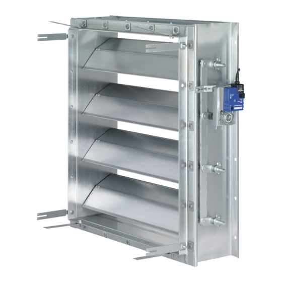
Fig. 1: Schematic illustration of JZ-HL and WG-JZ
①
Casing
②
Opposed blades (JZ-P*: parallel blades)
③
Blade tip seal (JZ-HL*, JZ-LL-* only)
④
Travel stop (angle section with seal) (JZ-HL*,
JZ-LL-*, only)
⑤
Actuator (optional)
⑥
Transverse link
Installation manual
Multileaf dampers
Type JZ-* / WG-JZ-*
Multileaf dampers Type JZ-* / WG-JZ-*
GB/en
⑦
External linkage
⑧
Crimped wire mesh, with or without insect
screen
⑨
WG border
⑩
WG bottom blade
⑪
WG regular blades
TROX GmbH
Heinrich-Trox-Platz
47504 Neukirchen-Vluyn, Ger-
many
Germany
Phone: +49 (0) 2845 2020
Fax: +49 (0) 2845 202265
E-mail: trox@trox.de
http://www.troxtechnik.com
1
Advertisement
Table of Contents

Subscribe to Our Youtube Channel
Related Manuals for Trox Technik JZ Series


Summary of Contents for Trox Technik JZ Series
- Page 1 Installation manual GB/en TROX GmbH Heinrich-Trox-Platz 47504 Neukirchen-Vluyn, Ger- many Germany Multileaf dampers Phone: +49 (0) 2845 2020 Fax: +49 (0) 2845 202265 E-mail: trox@trox.de Type JZ-* / WG-JZ-* http://www.troxtechnik.com Product overview Fig. 1: Schematic illustration of JZ-HL and WG-JZ ①...
-
Page 2: Important Notes
Important notes Important notes Limitation of liability Information on the installation manual The information in this manual has been compiled with reference to the applicable standards and This manual enables operating or service personnel guidelines, the state of the art, and our expertise to correctly install the product described below and and experience of many years. -
Page 3: Transport And Packaging
Transport and packaging Incorrect use Protect the unit from humidity, dust and con- tamination Storage temperature: -10 °C to 50 °C. WARNING! Relative humidity: 95 % max., no condensation Danger due to incorrect use! Installation Incorrect use of the unit can lead to dangerous situations. -
Page 4: General Installation Information
Installation General installation information NOTICE! Temperatures below the dew point Temperatures below the dew point should be avoided as they lead to condensation which may cause damage to the building structure. Duct installation Fig. 2: Installation types ① Ducts on both sides ②... - Page 5 Installation Wall/ceiling installation Installation with installation subframe Screw fix installation Fig. 5: Wall installation with installation subframe (steel/stainless steel construction) ① Threaded stud ② Fixing tab ③ Installation subframe Items 1 to 3 are included in the installation sub- frame supply package Fig.
- Page 6 Installation Assembling the installation subframe and damper Fig. 7: Wall installation with installation subframe (steel/stainless steel construction), height subdi- vided See Fig. 20 Fig. 9: Installation subframe and damper assembly ① Threaded stud ② Washer ③ Hexagonal nut ④ Fixing tab ⑤...
- Page 7 Electrical/pneumatic connection Connecting the duct Use screws to attach the damper to the ducting. The damper casing has flange holes for duct con- nection. Seal the joint between the casing flange and the duct in order to avoid pressure loss. Use sealing tape, for example, and clamps or additional screws, if necessary.
- Page 8 Electrical/pneumatic connection Electric open/close actuators TROX cannot guarantee leak-free dampers if the actuators are provided and installed by others. Connecting electric actuators Personnel: Skilled qualified electrician Use only cables that are designed for the supply voltage for which they will be used. The power rating is given on the actuator rating plate.
- Page 9 Electrical/pneumatic connection Limit switch Connecting pneumatic actuators Personnel: Skilled qualified electrician Given data Control medium: dust, oil-free and dry air as well as inert gases Supply voltage, depending on the solenoid Fig. 14: Connecting cable core identification for limit valve, see rating plate.
-
Page 10: Commissioning And Maintenance
Commissioning and maintenance Commissioning and maintenance Commissioning Personnel: HVAC technician As part of commissioning, the multileaf damper must be tested for correct functioning. NOTICE! JZ-LL-AL / JZ-HL-AL with quadrant stay JZ-LL-AL / JZ-HL-AL multileaf dampers have a quadrant stay which functions as a travel stop (open/close). -
Page 11: Technical Data
Technical data Technical data Multileaf dampers are manufactured according to the width (B) × height (H) ordered. Multileaf dampers must be installed according to B × H; turning them is not usually possible, Ä ‘Gen- eral installation information’ on page 4. Dimensions of JZ-* Fig. - Page 12 Technical data Dimensions of WG-JZ-* Fig. 22: WG-JZ Fig. 23: WG-JZ with actuator Attachments Dimension X [mm] Z12 - Z 51, ZF01 - ZF15, ZS21 - ZS22, ZS99 Z60 - Z77 Multileaf dampers Type JZ-* / WG-JZ-*...
- Page 13 Technical data JZ-S JZ-P JZ-S- JZ-P- JZ-AL JZ-LL JZ-HL JZ-LL- JZ-LL- JZ-HL- ● ● ● ● Steel, galv. ● ● ● Stainless steel ● ● ● Aluminium ● ● Parallel ● ● ● ● ● ● ● ● Opposed Closed blade air leakage 3 - 4 1 - 2 3 - 4...
- Page 14 Multileaf dampers Type JZ-* / WG-JZ-*...
- Page 15 Multileaf dampers Type JZ-* / WG-JZ-*...
- Page 16 Multileaf dampers Type JZ-* / WG-JZ-*...
Need help?
Do you have a question about the JZ Series and is the answer not in the manual?
Questions and answers