
Related Manuals for Trox Technik VARYCONTROL LVC


Summary of Contents for Trox Technik VARYCONTROL LVC
- Page 1 Installation and commissioning manual GB/en VAV terminal units VARYCONTROL LVC • TVE • TVR • TVJ • TVT • TZ-/TA-Silenzio TVZ • TVA • TVM • TVRK • TVLK Read the instructions prior to performing any task!
- Page 2 TROX GmbH Heinrich-Trox-Platz 47504 Neukirchen-Vluyn Germany Telephone: +49 (0) 2845 202-0 Fax: +49 (0) 2845 202-265 E-mail: trox@trox.de Internet: www.trox.de A00000071368, 2, GB/en 03/2020 © TROX GmbH 2018 VAV terminal units VARYCONTROL...
- Page 3 General information General information Safety notes Symbols are used in this manual to alert readers to Information about the installation and commis- areas of potential hazard. Signal words express the sioning manual degree of the hazard. This installation and commissioning manual enables Comply with all safety instructions and proceed carefully operating or service personnel to use the variable air to avoid accidents, injuries and damage to property.
- Page 4 General information Safety notes as part of instructions Safety notes may refer to individual instructions. In this case, safety notes will be included in the instructions and hence facilitate following the instructions. The above listed signal words will be used. Example: Loosen the screw.
-
Page 5: Table Of Contents
Table of contents Security ............. 6 Troubleshooting..........28 1.1 Correct use..........6 K values............29 1.2 Safety signs..........6 Control component/attachments....31 1.3 Residual risks..........6 Declaration of conformity....... 32 1.3.1 Electric shock hazards......6 1.4 System owner's responsibility..... 7 1.5 Staff............. -
Page 6: Security
Security Residual risks > Electric shock hazards Security Electrical voltage 1.1 Correct use VAV terminal units VAV terminal units are designed for variable volume flow control, restriction or shut-off in room air distribution and ventilation systems within closed rooms. Only skilled qualified electricians are allowed to work in areas marked as having electrical voltage. -
Page 7: System Owner's Responsibility
Security Personal protective equipment 1.4 System owner's responsibility HVAC technician HVAC technicians are individuals who have sufficient System owner professional or technical training in the field they are working in to enable them to carry out their assigned The system owner is a natural or legal person who for duties at the level of responsibility allocated to them and commercial or business purposes owns or manages the in compliance with the relevant guidelines, safety regu-... -
Page 8: General Safety Measures
Security Repair and replacement parts Safety shoes Safety shoes protect the feet from crushing, falling parts and prevent slipping on a slippery floor. 1.7 General safety measures Large temperature differences Be careful when there is a large temperature difference. Do not put the VAV terminal unit into operation immedi- ately if it has been transported from an unheated area to a warm one. -
Page 9: Transport, Storage And Packaging
Transport, storage and packaging Packaging Transport, storage and packaging Sharp edges and sheet metal parts CAUTION! Danger of injury from sharp edges and sheet metal parts. – Always wear protective gloves when handling the unit. Damage to the VAV terminal unit NOTICE! Risk of damage to the VAV terminal unit! –... -
Page 10: Product Description
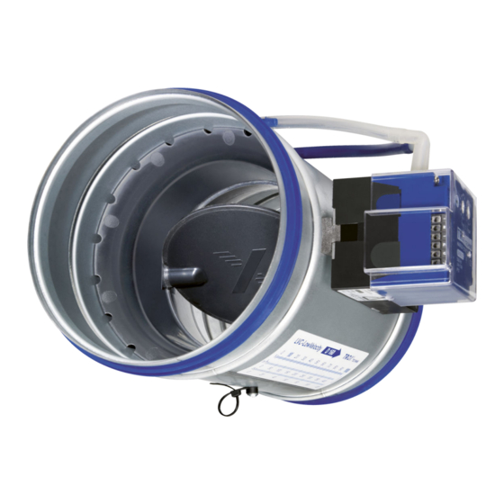
Product description VAV terminal unit types > Round VAV terminal units, steel Product description 3.1 VAV terminal unit types 3.1.1 Round VAV terminal units, steel Type Illustration Description ① Differential pressure sensor (plastic nozzle) ② Damper blade ③ Lip seal ④... -
Page 11: Rounded Vav Terminal Units, Plastic
Product description VAV terminal unit types > Rounded VAV terminal units, plastic 3.1.2 Rounded VAV terminal units, plastic Type Illustration Description ① Differential pressure sensor TVRK ② Damper blade ③ Casing ④ Actuator ⑤ Control components, e.g. a Universal con- troller ①... -
Page 12: Rectangular Vav Terminal Units, Steel
Product description VAV terminal unit types > Rectangular VAV terminal units, steel 3.1.3 Rectangular VAV terminal units, steel Type Illustration Description ① Differential pressure sensor ② Damper blade ③ Gear ④ Control components, e.g. Easy controllers ① Differential pressure sensor ②... - Page 13 Product description VAV terminal unit types > Rectangular VAV terminal units, steel Type Illustration Description ① Differential pressure sensor ② Lip seal ③ Inspection access ④ Damper blade ⑤ Integral sound attenuator ⑥ Control components, e.g. Easy controllers ① Integral sound attenuator ②...
-
Page 14: Detection Of The Control Components
Product description Position of the damper blade 3.2 Detection of the control compo- 3.3 Position of the damper blade nents The position of the damper blade corresponds to the mark on the axis and is thus recognisable from the out- The attached control component can be identified on side. -
Page 15: Installation
Installation Direction of airflow Installation 4.1 Security 4.3 Installation orientation Personnel: In the case of terminal units with diaphragm pressure transducers, the installation orientation of the control HVAC technician component must be observed; possible installation ori- Protective equipment: entations are indicated on a sticker (Fig. 6) on the ter- Protective gloves ... -
Page 16: Upstream Conditions
Installation Upstream conditions > Circular ducting Fig. 10: TVE Easy air direction arrow on the scale sticker 4.5 Upstream conditions The volume flow rate accuracy of VAV terminal units applies to a straight upstream section of the duct. Bends, junctions or a narrowing or widening of the duct cause turbulence that may affect measurement. -
Page 17: Rectangular Ducting
Installation Upstream conditions > Rectangular ducting 4.5.2 Rectangular ducting Upstream conditions with circular ducting ATTENTION: Observe air direction arrows on VAV Type Bend Junction Ä 15 terminal units during installation Observe EN 1505 for fittings and bridges, in partic- ... - Page 18 Installation Upstream conditions > Rectangular ducting Bend in horizontal ducting: TVJ, TVT Junction from horizontal main duct: TVJ, TVT Fig. 16: Junction from a horizontal main duct (view Fig. 13: Horizontal bend connection (view from from above) above) A junction causes strong turbulence. The stated A bend –...
-
Page 19: Affixing/Suspension
Installation Affixing/suspension > Rounded units 4.6.2 Rounded units Junction: TA-Silenzio, TVA Fig. 19: Convergence of two airflows The stated volume flow rate accuracy will be achieved even when the VAV terminal unit is connected at a junction and at the point of convergence of two air- flows. -
Page 20: Rectangular Units
Installation Affixing/suspension > Installation of secondary silencer 4.6.3 Rectangular units Fig. 22: Installation example directly on the terminal unit Terminal unit, rectangular, e. g. TVZ Air direction arrow e. g. on the order sticker Fig. 24: Examples of fixings for rectangular units Suspension, e. g. - Page 21 Installation Affixing/suspension > Installation of secondary silencer Secondary silencer TS Fig. 26: Installation of sound attenuator TX H = 100 mm VAV terminal unit TVJ-* / TVT-* Sound attenuator TX Splitter at bottom (TX behind TVJ / TVT in airflow Fig.
-
Page 22: Connecting The Duct
Installation Connecting the duct 4.7 Connecting the duct When connecting the ducting, the customer must ensure that the connection points are installed as air-tight as pos- sible in order to avoid negative influences from leakages such as air volume deviations, power consumption, etc. Unless otherwise specified, the connecting material is not included in the supply package. - Page 23 Installation Connecting the duct Rectangular duct TVZ / TVA / TVM / TZ-/TA-Silenzio Connection to ducting with air duct connections. Make sure that the flange seal and screw connection M8x16 (to be provided by others) are properly installed. Position the ducting exactly.
-
Page 24: Wiring
Wiring Installation notes Wiring Safety instructions DANGER! Danger of electric shock! Do not touch any live com- ponents! Electrical equipment carries a dangerous electrical voltage. – Only skilled qualified electricians are allowed to work on the electrical system. – Switch off the power supply before working on any electrical equipment. -
Page 25: Commissioning And Operation
Commissioning and operation Operation Commissioning and opera- – Airflow direction, according to airflow direction arrows Ä Chapter 4.4 ‘Direction of airflow’ tion on page 15 Ä Chapter – Upstream conditions correct, 6.1 Commissioning 4.5 ‘Upstream conditions’ on page 16 Electrical or pneumatic connections have been cor- ... -
Page 26: Volume Flow Rate Measurement
Commissioning and operation Volume flow rate measurement > Volume flow rate calculation 6.3 Volume flow rate measurement For testing the volume flow rate or differential pressure transducer, the differential pressure ∆p (effective pres- sure) can be measured directly at the differential pres- sure sensor of the air terminal unit by means of a pres- sure gauge (not on type TVE). -
Page 27: Maintenance
Maintenance Maintenance service Maintenance Check electrical feeder cables for damage and firm seating in the terminals. 7.1 System owner's responsibility Adjust the zero point of the differential pressure transducer, see the documentation for the elec- tronic control component. WARNING! Only authorised specialist personnel are allowed Zero point correction to perform the described maintenance measures. -
Page 28: Troubleshooting
Troubleshooting Troubleshooting Zero point correction performed on control compo- nents with static transducer? Check the installation situation If necessary, adapt the actuators again (only required for certain control components) Accessibility to the VAV terminal unit and the control ... -
Page 29: Values
K values K values Rectangular VAV terminal units Rounded VAV terminal units ØD C-Wert Serie [mm] [mm] [mm] (-> l/s) ØD C-Wert – 15,17 Serie [mm] (-> l/s) – 22,75 LVC 1) – – 30,34 LVC 1) – – 37,92 LVC 1) –... - Page 30 K values ØD C-Wert ØD C-Wert Serie Serie [mm] [mm] [mm] (-> l/s) [mm] [mm] [mm] (-> l/s) – 15,17 – – 9,97 – 22,75 – – 12,40 – 30,34 – – 16,00 – 37,92 – – 26,06 – 45,50 –...
-
Page 31: Control Component/Attachments
Control component/attachments Control component/attachments Controlled Differential pressure Code Actuator TVRK TVLK variable transducer Silenzio Silenzio Easy controller Dynamic Easy Integral Slow running, integrated ● ● ● ● ● ● ● ● ● Compact controller Dynamic Integral Slow running, integrated ●... -
Page 32: Declaration Of Conformity
Declaration of conformity VAV terminal units VARYCONTROL... - Page 33 Declaration of conformity Declaration of conformity VAV terminal units VARYCONTROL...
- Page 34 Declaration of conformity Declaration of incorporation according to the EU Machinery Directive 2006/42/EC, Annex II 1. B for partly completed machinery Manufacturer Person established in the Community authorised to compile the relevant technical documentation TROX GmbH Heinrich-Trox-Platz Jan Heymann, TROX GmbH DE - 47504 Neukirchen-Vluyn Description and identification of the partly completed machinery Product / Article...
- Page 35 VAV terminal units VARYCONTROL...
- Page 36 TROX GmbH +49 (0) 2845 202-0 Heinrich-Trox-Platz +49 (0) 2845 202-265 47504 Neukirchen-Vluyn E-mail: trox@trox.de © TROX GmbH 2018 Germany www.trox.de...
Need help?
Do you have a question about the VARYCONTROL LVC and is the answer not in the manual?
Questions and answers