Table of Contents
Advertisement
Quick Links
Advertisement
Table of Contents

Subscribe to Our Youtube Channel
Related Manuals for flowair EPECON LEO HD


Summary of Contents for flowair EPECON LEO HD
- Page 1 LEO HD | Water fan heater | Manual...
-
Page 2: Table Of Contents
Contents Important information ............................29 General information and purpose ........................30 PoluAl XT coating resistance table ........................31 Technical data and general dimensions ....................... 32 4.1. LEO HD S; LEO HD S INOX ................................32 4.2. LEO HD L; LEO HD L INOX ................................33 Installation and air ranges ..........................34 5.1. -
Page 3: Important Information
We have made every effort to make this manual as easy to understand as possible. However, if you have any difficulties, problems or questions, please contact FLOWAIR support at: info@flowair.pl. Also visit our website www.flowair.pl where you will find mounting tips. In this manual you will find important safety information and tips marked as below:... -
Page 4: General Information And Purpose
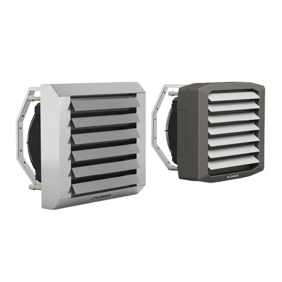
2. General information and purpose The LEO HD water heater is an executive element of a decentralized heating system for industrial buildings. Using the principle of forced convection, powered by a heating medium, it heats the ambient air through recirculation. Designed for heating facilities of various sizes. LEO HD is intended for construction facilities requiring devices with increased resistance to environmental conditions. -
Page 5: Polual Xt Coating Resistance Table
3. PoluAl XT coating resistance table Inorganic acids Max. concentration [ppm] Organic acids Max. concentration [ppm] Arsenic acid Acetic acid Boric acid Benzoic acid Hydrogen carbonate Lactic acid Chromic acid Phenols Bromic acid Citric acid Hydrochloric acid Fatty acids Hydrogen fluoride Formic acid Hydrogen sulphide Hydrocyanic acid... -
Page 6: Technical Data And General Dimensions
4. Technical data and general dimensions 4.1. LEO HD S; LEO HD S INOX LEO HD S LEO HD S INOX (AISI316L) LEO HD S AC LEO HD S EC Device Gear (AC) | Voltage set [V] (EC) Airflow [m /h]* 2000 1600... -
Page 7: Leo Hd L; Leo Hd L Inox
4.2. LEO HD L; LEO HD L INOX LEO HD L LEO HD L INOX (AISI316L) Device LEO HD L AC LEO HD L AC IP66 LEO HD L EC Gear (AC) | Voltage set [V] (EC) Airflow [m3/h]* 3800 2400 1400 3800 3500 2930 2300 1400 3000 2750 1850 Heating power (70/50/15oC) 20,8 15,8... -
Page 8: Installation And Air Ranges
5. Installation and air ranges 5.1. Arrangement methods and recommended distances Heaters can be mounted to vertical and horizontal partitions. During installation, maintain the recommended distances from the partitions presented below. LEO HD S LEO HD L A [m] min. 3 (see paragraph 5.2.) B [m] min. -
Page 9: Air Stream Speeds And Ranges
5.2. Air stream speeds and ranges 5.2.1. Isothermal ranges (LEO HD S AC; LEO HD S EC) Isothermal range (LEO HD S EC; LEO HD S AC) S EC - 10V S EC - 4V S AC - 3b S AC - 2b S AC - 1b Disntance from the heater [m] 5.2.2. -
Page 10: Non-Isothermal Ranges (Leo Hd S Ec; Leo Hd S Ac)
5.2.3. Non-isothermal ranges (LEO HD S EC; LEO HD S AC) Prędkość graniczna 0,5m/s LEO HD S EC - Non-isothermal range (1650m3/h) Distance from the heater[m] LEO HD S AC - Non-isothermal range(2000m3/h) Prędkość graniczna 0,5m/s Distance from the heater[m] Version V1.0... -
Page 11: Non-Isothermal Ranges (Leo Hd L Ec; Leo Hd L Ac/Ip66)
5.2.4. Non-isothermal ranges (LEO HD L EC; LEO HD L AC/IP66) Prędkość graniczna 0,5m/s LEO HD L EC - Non-isothermal range (3000m3/h) Distance from the heater [m] LEO HD L AC/IP66 - Non-isothermal range(3800m3/h) Prędkość graniczna 0,5m/s Distance from the heater [m] Version V1.0... -
Page 12: Rotating Console Installation
5.3. Rotating console installation Mounting screws (M8x20) are supplied with the rotating console. Before installing the heater, the must be unscrewed. Remember to tilt the air blades to ensure proper air flow. 5.4. Ceiling holders installation Ceiling holders are optional equipment. They should be installed of the corners of the heater. -
Page 13: Connecting The Hydraulic System
6. Connecting the hydraulic system 6.1. Hydraulic diagrams The diagrams presented below are examples only. The installation designer decides on the WARNING final shape and the use of individual elements. 6.1.1. Two-way valve SRQ2D 1/2” ZK–shut-off valve; ZO–vent valve; ZD–drain valve; FS–mesh filter; ZR–balancing valve; KP–flexible metal hose;... -
Page 14: Three-Way Valve Sqr3D 3/4" Supply Installation
6.1.4. Three-way valve SQR3D 3/4" supply installation ZK–shut-off valve; ZO–vent valve; ZD–drain valve; FS–mesh filter; ZR–balancing valve; KP–flexible metal hose; SRQ3d–three-way valve with on/off actuator 6.1.5. Three-way valve SRQ3D 1/2" return installation ZK–shut-off valve; ZO–vent valve; ZD–drain valve; FS–mesh filter; ZR–balancing valve; KP–flexible metal hose;... -
Page 15: Notes On Hydraulic Connections
6.2. Notes on hydraulic connections • Disconnect the heater power supply before connecting the water system. • The connection should be made without stress. It is recommended to use flexible ducts supplying the heating medium. • Water supply should be connected to the connector marked with red arrow. •... -
Page 16: Heating Medium Parameters
6.3. Heating medium parameters • The water heat exchanger can be supplied with water or glycol solutions up to 60%. • The heat exchanger tubes are made of copper, so heating medium should not cause corrosion of this material. • In particular, the parameters as below should be provided: Parameter Value... - Page 17 Tw1/Tw2 = 45/35 [°C] Tw1/Tw2 = 70/50 [°C] Tw1/Tw2 = 55/45 [°C] Δpw Δpw Δpw [°C] [kW] [°C] [l/h] [kPa] [kW] [°C] [l/h] [kPa] [kW] [°C] [l/h] [kPa] 3000 12,2 22,0 1063 20,5 30,0 17,4 27,0 1517 2750 11,6 22,5 1009 19,4 31,0...
-
Page 18: Electrical Diagrams
7. Electrical diagrams 7.1. TS (AC) control diagram 7.2. HMI (AC) control diagram Version V1.0... -
Page 19: Tra (Ac Ip66) Control Diagram
7.3. TRA (AC IP66) control diagram 7.4. 0-10V (EC) control diagram Version V1.0... -
Page 20: Bms (T-Box) (Ec) Control Diagram
7.5. BMS (T-box) (EC) control diagram 7.6. BMS (T-box) (AC) control diagram Version V1.0... -
Page 21: Drv Module Address Set
It is necessary to set the binary address on DIP-switch SW1 when connecting DRV modules to the T-box controller or BMS system. Each DRV control module connected to the FLOWAIR SYSTEM must have assigned an individual address. To assign it, with the power off set the device address according to the table below. -
Page 22: Bms Connection
7.6.3. BMS connection The DRV module allows you to connect the system to the BMS (Building Management System). The connection should be made with a three-wire cable (UTP twisted pair recommended) to the DRV IN connectors (diagram below). Version V1.0... -
Page 23: Start-Up, Operation And Maintenance
8. Start-up, operation and maintenance 8.1. Start-up • Before connecting the power supply check the correctness of connection of the fan motor and the controllers. These connections should be executed in accordance with their technical documentation. • Before connecting the power supply check whether the mains voltage is in accordance with the voltage on the device data plate. -
Page 24: Periodic Inspections
8.3. Periodic inspections • To keep proper technical parameters Flowair recommends periodic service (every 6 months) of fan heaters on behalf of the user. • Check heat exchanger, if is it filled with dirt or dust. If necessary - use pressurized air stream to clean the exchanger’s lamellas,... -
Page 25: Conformity With Weee Directive 2012/19/Ue
Running a business without harming the environment and observing the rules of proper handling of waste electrical and electronic equipment is a priority for FLOWAIR. The symbol of the crossed out wheeled bin placed on the equipment, packaging or documents attached means that the product must not be disposed of with other wastes. -
Page 26: Declaration Of Conformity
➂ 29.01.2024 ➀ Water heaters ➁ LEO HD S, LEO HD L; DECLARATION OF CONFORMITY UE ➃ FLOWAIR hereby confirms that fan heaters: • ➁ LEO HD S EC, LEO HD S AC • LEO HD L EC, LEO HD L AC, LEO HD L AC IP66 ➄...
Need help?
Do you have a question about the EPECON LEO HD and is the answer not in the manual?
Questions and answers