
Related Manuals for COMAC C120 BI-FUEL


Summary of Contents for COMAC C120 BI-FUEL
- Page 1 SCRUBBING MACHINES USE AND MAINTENANCE MANUAL ORIGINAL INSTRUCTION DOC. 10132672 VER.AA 12-2023...
-
Page 3: Table Of Contents
CONTENTS CONTENTS .................................. 3 GENERAL SAFETY REGULATIONS .......................... 5 SYMBOLS USED IN THE MANUAL ........................... 5 MAIN MACHINE COMPONENTS ..........................6 CONTROL PANEL COMPONENTS ........................7 PURPOSE AND CONTENT OF THE MANUAL ......................8 TARGET GROUP ................................. 8 STORING THE USE AND MAINTENANCE MANUAL ....................8 ON CONSIGNMENT OF THE MACHINE ........................ - Page 4 AUTOMATIC DETERGENT DOSING FUNCTION (VERSION WITH CDS) ............21 COURTESY LIGHTS (OPTIONAL) ........................21 WORK LIGHT FUNCTION ........................... 21 EMERGENCY STOP BUTTON ..........................22 BRAKING CONTROL ............................22 SOLUTION TANK CAPACITY LOW ........................22 DETERGENT TANK CAPACITY LOW ......................... 22 LIQUID VACUUM WAND KIT (OPTIONAL) ......................
-
Page 5: General Safety Regulations
The descriptions contained in this document are not binding. The company therefore reserves the right to make any modifications at any time to elements, details, or accessory supply, as considered necessary for reasons of improvement or manufacturing/commercial requirements. The reproduction, even partial, of the text and drawings contained in this document is prohibited by law. The company reserves the right to make any technical and/or supply modifications. -
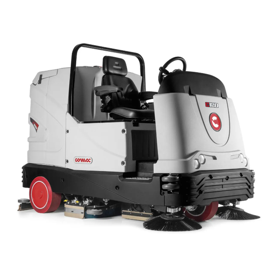
Page 6: Main Machine Components
MAIN MACHINE COMPONENTS 29 23 21 The machine's main components are the following: 24. Service brake pedal 25. Forward drive pedal 1. Seat 26. Detergent solution compartment drainage tube 2. Liquid vacuum wand. 27. Recovery solution compartment drainage tube 3. LPG cylinder compartment cover 28. -
Page 7: Control Panel Components
CONTROL PANEL COMPONENTS The control panel components on the Essential version are as follows: 1. Detergent solution flow adjustment knob 2. Low detergent solution level red warning light (valid for versions without the automatic detergent dosing kit), or low water level warning (valid for versions with the automatic detergent dosing kit) 3. -
Page 8: Purpose And Content Of The Manual
PURPOSE AND CONTENT OF THE MANUAL The aim of this manual is to provide customers with all the information needed to use the machine in the safest, most appropriate and most autonomous way. This includes information concerning technical aspects, safety, operation, downtime, maintenance, spare parts and scrapping. The operators and qualified technicians must carefully read the instructions in this manual before carrying out any operations on the machine. -
Page 9: Labels Used On The Machine
LABELS USED ON THE MACHINE Main switch symbol: Applied to the control panel, positioned on the front of the machine, to indicate the main switch. Acoustic signalling device control label: Applied in the vicinity of the steering column to indicate the acoustic signalling device's control button. Label for detergent solution tap command: Applied in the vicinity of the control column to identify the detergent solution tap's control lever. - Page 10 Liquid vacuum wand kit (optional) position label: Affixed to the machine to identify the liquid vacuum wand holder compartment. Label indicating the position of the detergent tank (CDS versions): Affixed to the machine to indicate the position of the detergent tank. Label indicating positioning of the cornering speed adjustment sensor: Affixed to the machine to explain how to correctly position the sensor which enables machine speed around corners to be reduced.
-
Page 11: Symbols Used On The Machine
Via Maestri del Lavoro, 13 37059 Santa Maria di Zevio (VR) declares under its sole responsibility that the products SCRUBBING MACHINES - mod. C120 BI-FUEL comply with the provisions of Directives: • 2006/42/EC: Machinery Directive. • 2014/30/EU: Electromagnetic compatibility directive. -
Page 12: Technical Data
TECHNICAL DATA C120 Bi-Fuel [KMS] Rated machine power 6430 Theoretical productivity up to sq.m./h 14300 Working width (scrubbing brush head) 1230 Working width (sweeping brush head) 1430 Volume of waste debris hopper Squeegee width 1350 Central brush head brushes (number -Ø external bristles) No. -
Page 13: Handling The Packaged Machine
HANDLING THE PACKAGED MACHINE Gross weight of machine with packaging is: • C120 Bifuel= 1053kg The overall dimensions of the package are: A= 1860 mm B= 2450mm C= 1610mm ATTENTION: It is recommended that all the packaging components be kept for any future machine transportation. -
Page 14: Preparation Of Machine
PREPARATION OF MACHINE BATTERY MAINTENANCE AND DISPOSAL For battery maintenance and recharging, respect the instructions provided by the battery manufacturer. When the batteries are dead, they must be disconnected by trained and specialised personnel. N.B.: dead batteries are classified as dangerous waste and as such must be delivered to an authorised body for disposal. TYPE OF FUEL TO BE UTILIZED In order to determine which fuel must be utilized to power the machine, please refer to the endothermic engine's use and maintenance manual. -
Page 15: Lpg Cylinder Replacement
WARNING: it is recommended to always wear protective gloves before handling fuel to avoid serious injuries to your hands. Fuels may contain substances similar to solvents. Avoid any contact of mineral oil products with the skin and eyes. Use gloves when refuelling. Change your protective clothes frequently, and clean them. -
Page 16: Filling The Solution Tank
ATTENTION: we recommend lifting and moving the cylinder only with lifting and transport means for its mass and size. 9. Remove the cylinder. 10. Position the new cylinder. 11. Connect the chain to secure the new cylinder. ATTENTION: remember to place the gasket between the LPG supply hose and the valve 12. -
Page 17: Inserting Water System Filter
ATTENTION: always use low-foam detergent. To avoid the production of foam, put a minimum quantity of anti-foam liquid in the recovery tank before starting to clean. Do not use pure acids. 6. Close the cap correctly to prevent liquid leaking out when working. 7. -
Page 18: Preparing To Work
NB: Fit the brush with red bristles at the rear of the sweeping brush head body. 6. Position the cover and tighten the knobs (Fig.22). 7. Close the casing (Fig.19). To fit the side brushes, carry out the operations described. 8. -
Page 19: Drive Select Selector
N.B.: Do not use the starter for more than 5 seconds at a time. If the engine does not start up, release the key and wait for 10 seconds before making a new attempt. 8. In order to ensure the machine's proper functionality, once the endothermic engine has been running for a few seconds, move the lever (1) to the end of its stroke (Fig.10). -
Page 20: Selecting The Operating Direction
SELECTING THE OPERATING DIRECTION The machine has a lever for selecting the travel direction (1) under the steering wheel (Fig.1). N.B.: To select the forward gear you need to first shift the lever up and then in the direction indicated by the arrow (Fig.2). N.B.: To go from forward to neutral, first move the lever in the direction indicated by the arrow (Fig.3). -
Page 21: Sweeping Brush Head Activation Function
WORK LIGHT FUNCTION The machine is equipped with front and rear working lights. To activate them, move the switch (1) on the control panel to the “I” position. NB: if the function is active, the corresponding green LED will be illuminated. N.B.: the sidelights come on when the machine is started. -
Page 22: Emergency Stop Button
EMERGENCY STOP BUTTON If any serious problems are encountered during the work operations, press the battery disconnect button (1) on the electrical system carter. CAUTION: This command interrupts the electrical circuit between the batteries and the machine system. N.B.: To recommence work having stopped and once the problem has been resolved, switch off the machine and turn the knob (1) in the direction of the arrows indicated on it. -
Page 23: Liquid Vacuum Wand Kit (Optional)
LIQUID VACUUM WAND KIT (OPTIONAL) Upon request, the machine can be fitted with the LIQUID VACUUM WAND system that vacuums up the detergent solution more accurately. To start it do as follows. 1. Using the knob (1) of the DS selector (Fig.1), select the “transfer” program. 2. -
Page 24: At The End Of The Work
AT THE END OF THE WORK At the end of the work, and before carrying out any type of maintenance, perform the following operations: 1. Using the "DRIVE SELECTION" selector knob on the control panel, select the “TRANSPORT” working program (A). The brush motors and solenoid valve will stop working, and after a few seconds the brush head bodies will lift up from the floor. -
Page 25: Recommended Maintenance Operations
RECOMMENDED MAINTENANCE OPERATIONS INTERVAL MACHINE COMPONENTS PROCEDURE Clean the vacuum chamber; the squeegee rubber blades; the vacuum nozzle (see Squeegee “CLEANING THE SQUEEGEE BODY”). Clean the scrubbing brush head body side splash guard rubber blades (see Scrubbing brush head body side “CLEANING THE SCRUBBING BRUSH HEAD SIDE SPLASH GUARD RUBBER splash guard rubber blades BLADES”). -
Page 26: Cleaning The Squeegee Body
CLEANING THE SQUEEGEE BODY The careful cleaning of the whole vacuum unit ensures better drying and cleaning of the floor as well as a longer vacuum motor life. To carry out the cleaning of the squeegee body, proceed as follows: 1. -
Page 27: Cleaning Of Sweeping Brush Head Body Brushes And Side Brushes
N.B. : the image (Fig.4) shows the direction of rotation for releasing the right brush. 7. Go to the front left-hand side of the machine and lift the casing (Fig. 5). 8. Remove the left splash guard, move the fixing anchors on the brush head body to the maintenance position (Fig.6). 9. -
Page 28: Emptying Of The Sweeping Brush Head Body Drawer
EMPTYING OF THE SWEEPING BRUSH HEAD BODY DRAWER For emptying proceed as follows: 1. Remove the drawer from the sweeping brush head body (Fig.1). 2. Empty the drawer. 3. Insert the drawer in the sweeping brush head body (Fig.2). DRAINING THE RECOVERY TANK Proceed as follows to empty the recovery tank: 1. -
Page 29: Emptying The Solution Tank
EMPTYING THE SOLUTION TANK Proceed as follows to empty the solution tank: 1. Remove the solution tank filler cap (Fig.1). 2. Remove the drainage hose of the solution tank from the clamps; it is located at the rear of the machine (Fig.2). 3. -
Page 30: Replacing The Squeegee Body Rubber Blades
REPLACING THE SQUEEGEE BODY RUBBER BLADES Ensuring the integrity of the squeegee body's rubber blades guarantees better floor cleaning and drying results, as well as a longer service life for the vacuum motor. In order to replace the squeegee body's rubber blades, do the following: 1. -
Page 31: Replacing The Scrubbing Brush Head Body Brushes
REPLACING THE SCRUBBING BRUSH HEAD BODY BRUSHES If the scrubbing brush head brushes are damaged they cannot work properly, or more specifically, they cannot remove the dirt from the floor; as such, the condition of these must be checked. To replace the scrubbing brush head brushes, proceed as follows 1. -
Page 32: Adjustment Interventions
ADJUSTMENT INTERVENTIONS ADJUSTING THE SQUEEGEE BODY'S RUBBER BLADES The careful adjustment of the squeegee body rubber blades guarantees better cleaning of the floor. To adjust the squeegee body blades, proceed as follows: 1. Sit on the driver’s seat. 2. Insert the key (1) into the main switch on the control panel. Set the main switch to "I" (Fig.1). 3. -
Page 33: Adjusting The Scrubbing Brush Head Side Splash Guard
ADJUSTING THE SCRUBBING BRUSH HEAD SIDE SPLASH GUARD If the side splash guards of the brush head body are not positioned correctly they cannot do their work properly, namely convey the dirty detergent solution towards the squeegee, therefore the height of the splash guard needs to be adjusted. This operation can be done with the brush head body in the work position, proceeding as follows: 1. -
Page 34: Choosing And Using Brushes
TYPE OF Ø BRIS- MACHINE CODE BRUSH- NOTES BRUSHES BRISTLES TLES 405562 430mm BLUE BRUSH 405563 430mm WHITE BRUSH 405564 430mm BLACK BRUSH C120 Bi-Fuel 405565 ABRASIVE 430mm GREY BRUSH 421819 430mm PAD HOLDER WITH CENTRE LOCK 455430 CYLINDRICAL BRUSH... -
Page 35: Troubleshooting
TROUBLESHOOTING This chapter lists the most common problems linked with the use of the machine. If you are unable to resolve the problems with the information given here, please contact your nearest assistance centre. PROBLEM POSSIBLE CAUSE SOLUTION Make sure that the main switch is at "I", if not The main switch is set to “0”... - Page 36 Debris trapped in the brushes. “CLEANING THE SCRUBBING BRUSH HEAD BODY BRUSHES” Contact a Comac assistance centre for help in Incorrect type of brush for the work to be choosing the type of brush to be used for the carried out.
- Page 37 NOTES...
- Page 38 NOTES...
- Page 40 COMAC S.p.A. Via Maestri del Lavoro, 13 - 37059 Santa Maria di Zevio - Verona - ITALY Tel. 045 8774222 - Fax 045 8750303 - www.comac.it - com@comac.it...
Need help?
Do you have a question about the C120 BI-FUEL and is the answer not in the manual?
Questions and answers