
Subscribe to Our Youtube Channel
Related Manuals for Tele Radio IO TRANSMITTER


Summary of Contents for Tele Radio IO TRANSMITTER
- Page 1 Tele Radio Finland Oy USER MANUAL IO_TRANSMITTER REV_1.7(ENG) IO_TRANSMITTER This user manual refers to: PCB (K1002) version 2.1 Firmware version 1.4 USER MANUAL Output PCB version 2.0...
- Page 2 DOCUMENT VERSION HISTORY Revision Date Notes 18.10.2022 Initial release. 22.11.2022 Changed to A5 format. Added Appendix. Minor updates in content. 9.1.2022 Added Relay PCB 12.1.2022 Minor updates in content. 16.2.2023 EMC Tests and technical data updates. 23.3.2023 Changed to Output PCB. Major changes in Menu structure. 21.12.2023 Firmware update.
-
Page 3: Table Of Contents
TABLE OF CONTENTS INTRODUCTION PREFACE REQUIRED SKILLS AND SAFETY WARRANTY TECHNICAL DATA ELECTRICAL CONNECTION OPERATION REGISTERING MENU CHANNEL (Menu Section 1) INPUT MODE (Menu Section 2) OFF DELAY I (Menu Section 3) OFF DELAY II (Menu Section 4) ON MASK I (Menu Section 5) ON MASK II (Menu Section 6) ANALOG/DIGITAL (Menu Section 7) 5.10... -
Page 5: Introduction
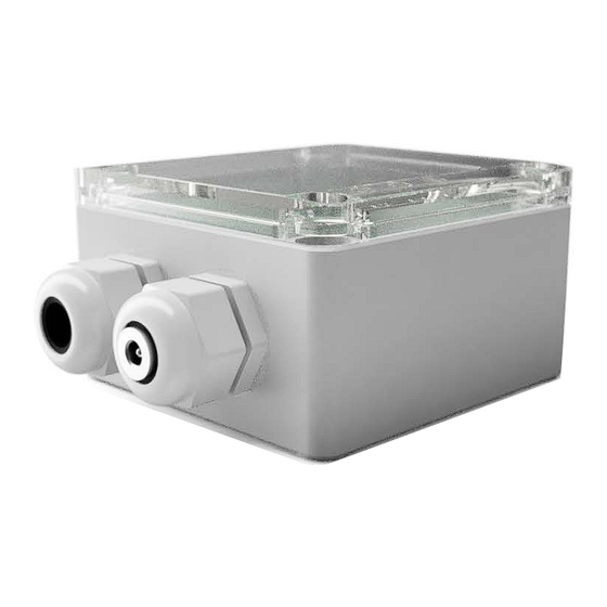
REV_1.7(ENG) INTRODUCTION The IO_Transmitter (IO_TX) is mainly designed to be used for transmitting signals from external sources to receivers within the IO_Series and Tele Radio Panther range. The transmitter be used with Digital and Analog sources. Digital, such as sensors (8-32V, High Level) and push buttons, switches or similiar (Gnd, Low Level) or Ana- log inputs 0.5-4.5V, 0-5V, 0-10V for Joysticks, Potentiometers and similiar. -
Page 6: Preface
The cabling should be designed and constructed according to best practice, an external fuse must be installed for the product’s power supply. Tele Radio Finland OY reserves the right to improve or change the product with- out further notice. WARRANTY... - Page 7 NOTE! The enclosure is rated IP66, however cable glands may be a subject of leakage and should be mounted pointing downwards. High pressure water cleaning is NOT recommended. For further instructions on service or repair, please contact Tele Radio Finland. Page 7...
-
Page 8: Technical Data
USER MANUAL IO_TRANSMITTER REV_1.7(ENG) TECHNICAL DATA Input Voltage 8-32 VDC (or 5 VDC) Current Consumption ~ 25 mA + (5V max 0.75 A) Inputs (IN_1-12) 12 pcs (DIGITAL); configurable LOW (0V) or HIGH (8-32V), 2 analog, 0-5V, 0.5-4.5V, 0-10V Reference Voltage Outputs 1 pc;... -
Page 9: Electrical Connection
USER MANUAL IO_TRANSMITTER REV_1.7(ENG) ELECTRICAL CONNECTION Output Board Connector Terminal Block J3 Connector Terminal Block J4 IO_TX Function J4-1 Ground J3-1 Ground J4-2 POT/EXT_IN 5V out/in (0,75A) J4-3 BATT+ Supply power (8-32VDC) J3-2* Input 12* J4-4 Supply ground J3-3* Input 11* J3-4 Input 10 All inputs are configurable HI or LO (see chapter... -
Page 10: Operation
USER MANUAL IO_TRANSMITTER REV_1.7(ENG) OPERATION By default the Display shows the active input. 1...9, A=10, B=11, C=12. The Dot (DP1) flashes when the transmitter is powered and also to indicate every new digit. During restart, the firmware version is displayed. Page 10... -
Page 11: Registering
USER MANUAL IO_TRANSMITTER REV_1.7(ENG) REGISTERING Registering means linking or joining a transmitter and a receiver. Make sure both are powered up before proceeding. To enter Register Mode: press the FUNCTION button - the Dot (DP2) lits - within 10 seconds, press the SELECT button - the transmitter is now in register mode. -
Page 12: Channel (Menu Section 1)
USER MANUAL IO_TRANSMITTER REV_1.7(ENG) CHANNEL (Menu Section 1) The transmitter can send on 14 different channels (12-25). To change channel press the SELECT button. If used in a dense wi-fi environments it’s recommended to use channels 15, 20, 25. Heavy traffic on wi-fi (802.11) channels 1, 6 and 11 may othervise cause some interference. -
Page 13: Off Delay I (Menu Section 3)
USER MANUAL IO_TRANSMITTER REV_1.7(ENG) OFF DELAY I (Menu Section 3) (Factory default: 0.0) The time Output 1 remains active after deactivating an input can be set from 0-1,5 seconds in steps of 0,1 seconds. To change Delay time press the SELECT button. OFF DELAY II (Menu Section 4) (Factory default: 0.0) The time Output 2 remains active after deactivating an input. -
Page 14: Analog/Digital (Menu Section 7)
USER MANUAL IO_TRANSMITTER REV_1.7(ENG) ANALOG/DIGITAL (Menu Section 7) (Factory default: DI) To change between Digital or Analog inputs press the SELECT button. In DIGITAL Mode, all inputs are digital. In any ANALOG mode, inputs 11 & 12 are analog, inputs 1-10 are digital and the transmitter sends in continous mode. -
Page 15: Approvals And Safety
USER MANUAL IO_TRANSMITTER REV_1.7(ENG) APPROVALS AND SAFETY EMC TESTS Emission tests according to the test specification EN 61000-6-3: residential, commersial and light industry. Emission test Test method Conclusion Radiated disturbance CISPR 16-2-3 (2016+AMD1:2019) Pass Conducted disturbance at mains ports CISPR 16-2-1 (2017-06 ed. 3.1) Pass Immunity tests according to the test specification EN 61000-6-2: industrial environment. - Page 16 -9V, -6V, 10 pulses Profile Load Dump, 123V, 10 pulses 56V, 5 pulses unclamped ISO 10605 Electrostatic Discharge (ESD) 330pF Air Discharge Contact Discharge Indirect Discharge ±8.0kV ±6.0kV ±6.0kV (For more detailed reports, please contact Tele Radio Finland) Page 16...
-
Page 17: Environmental Tests
USER MANUAL IO_TRANSMITTER REV_1.7(ENG) ENVIRONMENTAL TESTS The enclosure is certified according to EN 62208:2011:2011 Degree of protection (EN 60529) IP66 / IP67 Mechanical strength (EN 62262) IK08 +35 oC / -40 oC Material Polycarbonate DIMENSIONS AND MOUNTING When mounting the transmitter in moist or otherwise harch environments, make sure that the cable glands are pointing downwards. -
Page 18: Regulatory Information
This product conforms with the regulatory requirements for the UKCA (UK Conformity Assessed) marking. The latest version of the complete UK Declaration of Conformity is available on request from Tele Radio Finland Oy or from the website www. radio-remote.com Page 18... - Page 19 USER MANUAL IO_TRANSMITTER REV_1.7(ENG) IMPORTANT: Contains FCC ID: VW4A091729. This equipment complies with Part 15 of the FCC Rules. Operation is subject to the following two conditions: (1) this device may not cause harmful interference, and (2) this device must accept any interference received, including interference that may cause undesired operation (FCC 15.19).
- Page 20 USER MANUAL IO_TRANSMITTER REV_1.7(ENG) This equipment complies with radio frequency exposure limits set forth by Industry Canada for an uncontrolled environment. This equipment should be installed and operated with minimum distance 20 cm between the device and the user or bystanders. Cet équipement est conforme aux limites d’exposition aux radiofréquences définies par Industrie Canada pour un environnement non contrôlé.
-
Page 21: Appendix A: Declaration Of Conformity Eu
USER MANUAL IO_TRANSMITTER REV_1.7(ENG) APPENDIX A: Declaration of Conformity EU Page 21... -
Page 22: Appendix B: Declaration Of Conformity Uk
USER MANUAL IO_TRANSMITTER REV_1.7(ENG) APPENDIX B: Declaration of Conformity UK Page 22... -
Page 23: Appendix C: Button_Flex
USER MANUAL IO_TRANSMITTER REV_1.7(ENG) APPENDIX C: BUTTON_FLEX The Button_Flex is an easy way to add extra push-button functions to a joystick or any other similiar controlling unit. Available in 3- or 6-button versions with a 1,5m cable and connector that fits directly into the IO_Transmitter’s connector J1 or J2. -
Page 24: Appendix D: Replacing The T2182 (Wall Transmitter)
USER MANUAL IO_TRANSMITTER REV_1.7(ENG) APPENDIX D: REPLACING THE T2182 (WALL TRANSMITTER) J3 connector corresponding to T2182 connector: 1 2 3 4 5 6 7 8 9 10 11 12 IO_TX T2182 Function J3-1 Ground J3-2 Input 12 J3-3 Input 11 J3-4 Input 10 J3-5... -
Page 25: Appendix E: Wiring- And Applications Examples
USER MANUAL IO_TRANSMITTER REV_1.7(ENG) APPENDIX E: WIRING- AND APPLICATIONS EXAMPLES IO_TX PN-R8-1 Connector J3 Connector J4 Example 1: 8-32V Supply. Transmitting low side input (Digital In 1 and 2) to Panther receiver. Connector J3 Connector J4 Example 2: 8-32V Supply. Transmitting high side input (Digital In 1) to Panther receiver. - Page 26 USER MANUAL IO_TRANSMITTER REV_1.7(ENG) Connector J3 Connector J4 Example 4: 8-32V Supply. Transmitting input from Joystick (Analog In) to Panther receiver. Set Analog/Digital to Analog 0,5-4,5V in Menu Section 7. Connector J3 Connector J4 Example 5: 8-32V Supply. Transmitting input from Potentiometer (Analog In) to Panther receiver.
-
Page 27: Appendix F: Product Codes
USER MANUAL IO_TRANSMITTER REV_1.7(ENG) APPENDIX F: PRODUCT CODES Following products codes may be ordered as is. Other versions or combinations upon request from Tele Radio Finland Oy. 500-005-382-02 IO_TX IO_SERIES Transmitter, 12 inputs, 8-32VDC 500-005-426-14 IO_TX BF3 CHA IO_SERIES Transmitter + Button_flex_3 + Cig plug... - Page 28 Tele Radio Finland Oy Business ID FI28635227 Address: Gerbyntie 14 65230 Vaasa, Finland Telephone: +358 20 144 3030 E-mail: info@radio-remote.com For more information, visit our web site: www.radio-remote.com...
Need help?
Do you have a question about the IO TRANSMITTER and is the answer not in the manual?
Questions and answers