Table of Contents
Advertisement
Quick Links
No. DOC1080290
NN67563400
PRODUCT NAME
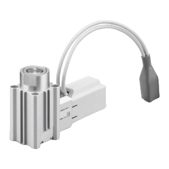
Electric Stopper Cylinder / Controller Type
MODEL / Series / Product Number
LEBQ32・50-X1 Series
Controller
JXC
Series
#This manual describes the actuators operation in combination with the JXC series controllers.
#Refer to the manual relevant to the controller being used for full operating instructions.
Advertisement
Table of Contents

Related Manuals for SMC Networks LEBQ32-X1 Series


Summary of Contents for SMC Networks LEBQ32-X1 Series
- Page 1 No. DOC1080290 NN67563400 PRODUCT NAME Electric Stopper Cylinder / Controller Type MODEL / Series / Product Number LEBQ32・50-X1 Series Controller JXC Series #This manual describes the actuators operation in combination with the JXC series controllers. #Refer to the manual relevant to the controller being used for full operating instructions.
-
Page 2: Table Of Contents
Contents 1. Product Specifications ................3 1.1 How to Order ..........................3 1.2 Specification ..........................4 1.3 Dimensions ............................. 5 1.4 Construction ..........................7 2. Electric Actuators Precautions ..............8 Wiring of cables / Common precautions ..................8 Electric actuators / Common precautions ................10 Design and selection ...................... - Page 3 LEBQ Series/ Electric Stopper Cylinder Safety Instructions These safety instructions are intended to prevent hazardous situations and/or equipment damage. These instructions indicate the level of potential hazard with the labels of “Caution,” “Warning” or “Danger.” They are all important notes for safety and must be followed in addition to International Standards (ISO/IEC) , and other safety regulations.
- Page 4 LEBQ Series/ Electric Stopper Cylinder Safety Instructions Caution We develop, design, and manufacture our products to be used for automatic control equipment, and provide them for peaceful use in manufacturing industries. Use in non-manufacturing industries is not covered. Products we manufacture and sell cannot be used for the purpose of transactions or certification specified in the Measurement Act.
-
Page 5: Product Specifications
1. Product Specifications 1.1 How to Order How to order is shown below. LEBQ □ 32 □ - 20 □ □ - □ □ - X1 (1) (2) (3) (4) (5) (6) (7) (8) (1) Mounting (3) Stopper direction A Ends tapped B... -
Page 6: Specification
1.2 Specification The basic specifications of this product are shown below. Model LEBQ32-X1 LEBQ50-X1 Stroke [mm] Speed [mm/s] Screw lead [mm] 150/30 Impact/Vibration resistance [m/sec2] Actuation type Slideing screw + Cam Operating temperature range [℃] 5~40 Operating humidity range [%RH] 90 or less (No condensation and freezing) □28 □42... -
Page 7: Dimensions
1.3 Dimensions – 5 –... - Page 8 – 6 –...
-
Page 9: Construction
1.4 Construction Component Parts Description Material Note Cylinder tube Aluminium alloy Anodized Rod cover assembly Piston rod Carbon steel Hard chrome plating Cam receiver Aluminium alloy Anodized Housing Aluminium alloy Anodized Motor cover Synthetic resin "With cover" only Roller Synthetic resin "Roller type"... -
Page 10: Electric Actuators Precautions
2. Electric Actuators Precautions Wiring of cables / Common precautions Warning Adjustment, installation, inspection, or wiring changes should be conducted after the power supply to this product has been turned off. Electrical shock, malfunction, or damage can result. Never disassemble the cable. Use only the specified cables. Never connect or disconnect the cable or connector with the power on. - Page 11 11. The speed and force may change depending on the cable length, load, and mounting conditions. Furthermore, if the cable length exceeds 5 m, then it will decrease by up to 10% for every additional 5m. (At 15 m: Reduced by up to 20%) 12.
-
Page 12: Electric Actuators / Common Precautions
Electric actuators / Common precautions Design and selection Warning Be sure to read the operation manual (this manual and the one for the controller: LEC/JXC series). Handling or usage/operation other than that specified in the operation manual may lead to breakage or operation failure of the product. - Page 13 Caution Operate within the limits of the maximum usable stoke. The product will be damaged if it is used with a stroke which exceeds the maximum stroke. Refer to the specifications of the product. When the product repeatedly cycles with partial strokes, operate it at a full stroke at least once a day or every 1000 strokes.
-
Page 14: Mounting
Mounting Warning Keep the manual in a safe place for future reference. The product should be mounted and operated only after thoroughly reading the operation manual and understanding its contents. Observe the tightening torque for screws. Tighten the screws to the recommended torque for mounting the product. Do not make any alterations to this product. -
Page 15: Handling
Handling Warning Do not touch the motor during operation. The surface temperature of the motor can increase to approx. 80°C due to operating conditions. The temperature may also increase due to energization. As it may cause burns, do not touch the motor when in operation. - Page 16 [Grounding] Warning Be certain to ground the actuator. Dedicated grounding should be used. Grounding should be to a D-class ground. (Ground resistance of 100 Ω or less.) Grounding should be performed near the actuator to shorten the grounding distance. The cross-sectional area of this wire shall be a minimum of 2 mm Avoid common grounding with other devices.
-
Page 17: Operating Environment
Operating environment Warning Avoid use in the following environments. a. Areas with large amounts of dust or cutting chips that could enter the product b. Areas where the ambient temperature exceeds the specified range (Refer to the specifications.) c. Areas where the ambient humidity exceeds the specified range (Refer to the specifications.) d. -
Page 18: Maintenance
Maintenance Warning Do not disassemble or repair the product. Fire or electric shock can result. Contact SMC if the disassembly of the product is required for maintenance. Before modifying or checking the wiring, the voltage should be checked with a tester 5 minutes after the power supply has been turned off. -
Page 19: Actuator With Lock / Common Precautions
Actuator with Lock / Common precautions Warning Do not use the lock as a safety brake or as a control that requires a locking force. The lock used for the product with lock is designed to prevent the dropping of workpieces. For vertical mounting, use the product with lock. -
Page 20: Controller ( Including Driver ) And Peripheral Devices / Common Precautions
Controller ( Including Driver ) and Peripheral Devices / Common precautions Design and selection Warning Be sure to apply the specified voltage. Otherwise, malfunction or breakage may occur. If the applied voltage is lower than the specified voltage, it is possible that the load will not be able to be moved due to an internal voltage drop of the controller. Please check the operating voltage before use. - Page 21 13. Radiant heat from strong heat sources, such as a furnace, direct sunlight, etc., should not be applied to the product. It will cause failure of the controller or its peripheral devices. 14. Do not use the product in an environment subject to a temperature cycle. It will cause failure of the controller or its peripheral devices.
-
Page 22: Installation
Installation Warning Install the controller and its peripheral devices on a fire-proof material. Direct installation on or near a flammable material may cause a fire. Do not install the product in a place subject to vibrations and impacts. It will cause failure or malfunction. Do not mount the controller and its peripheral devices together with a large-sized electromagnetic contactor or no-fuse breaker, which generate vibration, on the same panel. -
Page 23: Wiring
Wiring Warning Do not apply any excessive force to cables, such as repeated bending, tensioning, or placing a heavy object on the cables. It may cause an electric shock, fire, or the breaking of a wire. Connect wires and cables correctly. Incorrect wiring could break the controller or its peripheral devices depending on the seriousness. -
Page 24: Electric Stopper Cylinder /Specific Product Precautions
3. Electric Stopper Cylinder /Specific Product Precautions 3.1 Design and selection Warning Do not apply excessive external force to the motor. Miss-alignment of the motor may lead to signal detection error, increasing internal friction or damage to the motor. Use within the specified range. If the condition exceeds the specified operating range, it will cause excessive impact or vibration to the actuator, leading to possible damages. -
Page 25: Mounting
3.2 Mounting Caution Do not drop or hit the electric stopper cylinder to avoid scratching and denting the mounting surfaces. Scratches and gouges may malfunction. Do not apply rotational torque to the cylinder piston rod. Align the cylinder so that it is parallel to the working face of the work in order to prevent rotational torque acting on the cylinder piston rod. -
Page 26: Handling
3.3 Handling Warning Do not put your hand or finger between the lever holder and rod cover. Do not put your hand or finger between the lever holder and the rod cover when lowering the cylinder during adjustment of the shock absorber. Caution INP output signal for Positioning operation When the product comes within the set range by step data [In positon], output signal will be... - Page 27 How to adjust the lever type (adjustable absorber type) model For the lever type (adjustable absorber type) model, strokes of the shock absorber can be adjusted with an adjustment bolt included in order to stop in accordance with the transfer conditions. Follow the procedures below to adjust strokes.
-
Page 28: Maintenance
3.4 Maintenance Warning Perform maintenance inspection according to the procedures indicated in the operation manual. If handled improperly, malfunction and damage of machinery or equipment may occur. Caution The stopping condition of the transferred object may vary due to changes in ambient temperature or changes in the shock absorber resistance over time. - Page 29 Tighten the 2 hexagon socket head set screws to securethe non-rotating guide. When tightening, apply screwlocking adhesive to the hexagon socket head set screws. ∗ Tightening torque: 0.63 [N・m] ∗ The non-rotating guide is secured with 2 hexagon socket head set screws. If 1 of the screws is overtightened, the non-rotating guide may come into contact with the piston rod, resulting in a malfunction.
-
Page 30: Troubleshooting
4. Troubleshooting Alarms below are an abstract of representative examples. For other alarms, refer to the controller operation manual. Phenomenon Cause Countermeasure Fall to operate The cable is not connected or has been Confirm that the cable is connected During / Initial stage correctly. - Page 31 Phenomenon Cause Countermeasure “Posn failed/code: 1-149” is The lead screw had friction due to Operate within the specified generated. range. During excessive external force (including ↓ operati vibration) or impact. <Procedure for restart> The Power supply does not have Check the power consumption Controller version/SV1.0 for each actuator and controller:...
- Page 32 Phenomenon Cause Countermeasure Alarm for "Over motor The power supply is a "restricted inrush- Replace the power supply with Vol/code: 1-145" is current type", therefore an alarm has been a ”nonrestricted inrush-current generated. generated due to voltage drop. type” power supply. ↓...
- Page 33 Revision history No. DOC1080290 June 2024 First edition 4-14-1, Sotokanda, Chiyoda-ku, Tokyo 101-0021 JAPAN Tel: + 81 3 5207 8249 Fax: +81 3 5298 5362 http://www.smcworld.com Note: Specifications are subject to change without prior notice and any obligation on the part of the manufacturer. ©...
Need help?
Do you have a question about the LEBQ32-X1 Series and is the answer not in the manual?
Questions and answers