
Related Manuals for SMC Networks LECPMJ Series


Summary of Contents for SMC Networks LECPMJ Series
- Page 1 Doc.No. JXC※-OMT0062-A PRODUCT NAME CC-Link Direct Input Type Step Motor Controller (Servo / 24 VDC) MODEL / Series / Product Number LECPMJ Series...
- Page 2 Contents 1. Safety Instructions ................5 2.Product Outline ................7 2.1 Product features ............................7 2.2 Product configuration ..........................8 2.3 How to Order ..............................9 2.4 Option ................................10 (1)Actuator cable (5m or less) ......................10 (2) Actuator cable (8-20m) ........................10 (3) Actuator cable for with lock and sensor (5m or less) ............
- Page 3 4.1 Switch (STATION NO., B RATE)......................23 4.2 Parameter Setting ............................24 4.3 PLC Setting ..............................25 5. External Wiring Diagram............... 26 5.1 CN1: Power connector ..........................26 5.2 CN2: Motor power connector and CN3: Encoder connector ..........26 5.3 CN4: Serial I/O connector........................26 (1) Connection with the teaching box ....................
- Page 4 10.1 Remote IO (Rx and Ry) ......................... 42 10.2 Remote register (RWr and RWw) ....................48 11. Setting Data Entry ............... 59 11.1 Step data ..............................59 11.2 Basic parameter ............................62 11.3 Return to origin parameter ......................... 65 11.4 Operation parameters ........................... 66 12.
- Page 5 17. Wiring of cables/Common precautions ........89 18. Electric actuators/Common precautions ........90 18.1 Design and selection ..........................90 18.2 Mounting ..............................91 18.3 Precautions for Use ..........................91 18.4 Operating environment ........................93 18.5 Maintenance ............................... 93 18.6 Precautions for electric actuator with lock ................94 19.
- Page 6 LECPMJ Series / Controller 1. Safety Instructions These safety instructions are intended to prevent hazardous situations and/or equipment damage. These instructions indicate the level of potential hazard with the labels of “Caution,” “Warning” or “Danger.” They are all important notes for safety and must be followed in addition to International Standards (ISO/IEC)*1), and other safety regulations.
- Page 7 LECPMJ Series / Controller 1. Safety Instructions Caution The product is provided for use in manufacturing industries. The product herein described is basically provided for peaceful use in manufacturing industries. If considering using the product in other industries, consult SMC beforehand and exchange specifications or a contract if necessary.
- Page 8 2.Product Outline 2.1 Product features The followings are the main functions of this controller: Connect with CC-Link Operation from CC-Link, reading information and writing are possible by connecting with CC-Link. Electric Actuator Control Positioning operation and Pushing operation, at a specific speed and force, of the electric actuator are possible by controlling the Step motor (24 VDC servo).
- Page 9 2.2 Product configuration The product configuration of this controller is as follows. ● Electric actuator * CC-Link Terminating Prepared by user resistance Communication plug connector *3) *4) LEC-CMJ-□ Power supply ● 24 VDC Controller to CN5 *1) *6) ●Actuator cable ●Controller setting kit *2) *5) Part No: LE-CP-□-S...
- Page 10 2.3 How to Order The product configuration of this controller is as follows. L E C P M J □ □ - □ Controller Electric actuator model Compatible Stroke example:For LEFS25B-100B-S3MJT, Specify LEFS25B-100 Step motor (Servo / 24 VDC) Rotating angle:For LER10K-2L-RMJT, Specify LER10K-2 Kind of controller (Enter from the electric actuator part number...
- Page 11 2.4 Option (1)Actuator cable (5m or less) LE-CP- □- □ ① ② Cable color Terminal no. signal Terminal no. Brown Cable length (L) Orange Yellow 1.5m Green COM-A/COM Blue COM-B/ - ③ Shield Cable color Terminal no. Brown Black Actuator cable type Black Robotic type cable...
- Page 12 (3) Actuator cable for with lock and sensor (5m or less) ② ① LE- CP- □- B- □ Cable color Terminal no. signal Terminal no. Brown Cable length (L) Orange Yellow 1.5m Green COM-A/COM COM-B/ - Blue ③ Shiel Cable color Terminal no.
- Page 13 (5) Communication plug connector LEC- CMJ- □ Correspondence network Type CC-Link Straight type T-Branched Straight type type Name Function CC-Link communication line A CC-Link communication line B CC-Link ground line CC-Link shield T-Branched type Frame ground (6) Controller setting kit LEC- W2...
- Page 14 (7) Teaching box LEC-T1-3JG □ Teaching box Enable switch Cable length No enable switch Equipped with enableswitchchluded. Initial language English Stop switch Japanese Equipped with stop switch Dimensions No. Name Function A screen ofliquid crystal display (with backlight) Ring A ring for hanging the teaching box.
- Page 15 2.5 Startup Procedures Be sure to check the procedure below before use. (1) Confirmation of the package content After unpacking everything, check the description on the label to identify the controller and the number of accessories. If any parts are missing or damaged, please contact your distributor. Item Quantity Controller...
- Page 16 (6) Power ON alarm (error) Ensure the stop is not activated and then supply 24 VDC power. Function LED color Status Green Normal No alarm controller Please refer to “8. LED Display” for the explanation of each LED lamp If the LED [PWR] lights in green, the controller is in the normal condition. However, if the LED [ALM] lights in red, the controller is in the alarm (error) condition.
- Page 17 (8) Operation pattern setting Set up the step data and parameters using the controller set up kit or the teaching box. ●Controller set up kit ●Teaching box Please refer to the manuals of the controller setting software or the teaching box for how to setup the operation pattern.
- Page 18 3. Product Specifications 3.1 Specifications (1) Basic specifications Item Specifications Compatible motor Step Motor (Servo / 24 VDC) Power voltage: 24 VDC +/-10% *1) *2) Power supply Max. current consumption: 3A (Peak 5A) (for both of motor drive power control power, stop, lock brake release) Compatible encoder Incremental A/B phase (800 pulse / rotation) Serial communication...
- Page 19 (2)CC-Link type Item Specifications Field bus CC-Link Version 1.10 Station type Remote device station Number of stations 1 stations 2 stations 4 stations Occupied number of Number of input points/ 32 points / 32 points 64 points / 64 points 128 points /128 points stations number of output points...
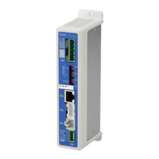
- Page 20 3.2 Parts description The detailed descriptions of each part are as follows: Side (Controller version) SV1.00 (10) ARX830007 Label of Controller version Example) SV2.07-1.00 (11) A Side Label Name Description LED to indicate the condition of the controller. Please refer to the “8. LED Display” Communication plug Used to connect the CC-Link line.
- Page 21 3.3 Outside dimension diagram The outside view of this product is as shown in the diagram below: (1) Screw mount type (LECPMJ□-□) (2) DIN rail mount type (LECPMJ□D-□) - 20 -...
- Page 22 3.4 How to install (1) How to install The controller can be direct mounted using screws or mounted on a DIN rail. The followings are the descriptions on how to install each type: 1) Screw mount type (LECPMJ□-□) 2) DIN rail mount type (LECPMJ□D-□) (Installation with two M4 screws) (Installation with the DIN rail) DIN rail is locked...
- Page 23 Caution The earthling should be the dedicated grounding point. It should be a functional ground with less than 100 Ω resistance. The cross section of the grounding wire should be greater than 2mm The ground point should be near this controller to make the wire length shorter. Other device Controller Controller...
- Page 24 4. Initial Setting 4.1 Switch (STATION NO., B RATE) Set the CC-Link address and the CC-Link communication speed by the rotary switch. The table below shows functions of switches. The station No. of CC-Link is shown. (01 to 64) The communication speed of CC-Link is shown. ●STATION NO Switch name Set range...
- Page 25 (1) Since the CC-Link communication speed of the PLC is 10 Mbps, set the B RATE switch for all controllers to 4 (10 Mbps). (2) Set the controller’s STATION NO. (for the PLC, set the CC-Link station No. address to 0.) Controller 1:...
- Page 26 4.3 PLC Setting Set PLC that become the master station. Use a PLC that supports CC-Link Ver. 1.10 or Ver. 2.00. Show a case with CC-Link system master local unit (Q Series) of Mitsubishi for the example about setting. PC series: QCPU (Q mode), PC type: Q00UJ ●...
- Page 27 5. External Wiring Diagram Examples of standard wiring are shown for each connector (CN1 to CN5) of the controller. 5.1 CN1: Power connector Controller Controller power supply 24 VDC Power cable (The 24 VDC power supply and the power cable should be obtained separately.) Please refer to “6.
- Page 28 (2) Connection with a PC Controller setting kit Controller Conversion unit モニタ モニタ 120.3 120.3 現在 位 置 現在 位 置 動 作中 動 作中 現在 速 度 現在 速 度 mm/s mm/s ア ラーム ア ラーム 設定 設定 位 置 位...
- Page 29 6. CN1: Power supply connector details 6.1 Power supply plug specifications Power supply plug Terminal Function Descriptions The negative common power for M 24V, C 24V, EMG Common power (-) and BK RLS. The positive power for the electric actuator motor to be M 24V Motor power (+) supplied via the controller.
- Page 30 6.3 Wiring of power supply plug Connect the power supply plug to the 24 VDC controller power supply according to instructions (1) (2) and (3) and then, insert it into the CN1 connector of the controller. (1) Wiring of the power supply Connect the positive of the 24 VDC controller power supply of the controller to the C 24V, M 24V and EMG terminal of the power supply connector, and connect the negative of that power supply to the 0V terminal.
- Page 31 (3) Wiring of the lock release Install an unlocking switch for adjustment or recovery during an emergency of the electric actuator with lock. The switch (24 VDC, Contact capacity: 0.5A or more) should be obtained separately. One terminal of the lock release switch should be connected to the 24 VDC power supply and the other should be connected to the BK RLS terminal.
- Page 32 6.4 Stop circuits When the external switch to stop or the stop switch of the teaching box is enabled on this controller, the electric actuator will stop. (1) Example circuit 1- Single controller with teaching Box When the teaching box is connected to the controller, the teaching box’s stop switch will become effective.
- Page 33 (2) Example circuit 2 - multiple controllers If the system where this controller is installed has a stop circuit for whole system, or if the system has multiple controllers with individual power supply, relay contacts should be made between the 24 VDC controller power supply and the EMG terminal of the power supply plug.
- Page 34 (3) Example circuit 3 - Motor power shutdown If there is a necessity to have circuit to shut down the motor power externally, relay contacts should be made between the 24 VDC controller power supply and the M 24V and EMG terminal of the power supply plug.
- Page 35 7. CN5: Communication Plug Connector 7.1 Wiring The communication plug connector specification of the optional product is shown below. Straight type T-Branched type LEC-CMJ-S LEC-CMJ-T Manufactured by Phoenix Contact Manufactured by Phoenix Contact Part no:MSTB2,5/5-ST-5,08 AU Part no:TMSTBP2,5/5-ST-5,08 AU Designation Description CC-Link communication line A CC-Link communication line B...
- Page 36 7.2 Electric wire specification Item Specifications Applicable wire size AWG 24 to 12 (0.2 to 2.5mm (Single line, stranded wire) The rated temperature for the insulation coating: 60 C or more LEC-CMJ-S:7mm Stripped section length LEC-CMJ-T:10mm 7.3 Wiring of communication plug connector Please wire the CC-Link communication cable to the communication plug connector, and then insert it into CN5 connector of controller.
- Page 37 8. LED Display 8.1 LED display Details of the LED display are shown as follows. Content name Power is not supplied Power supply and EEPROM Green On Power is supplied writing status Green flashing EEPROM writing Normal status Alarm status. Red On Alarm is generated Normal status...
- Page 38 9. Mode 9.1 Outline This controller has 3 types of operation mode (Single numerical data instructions, Half numerical data instructions, Full numerical data instructions). These modes can be changed by registering the occupied number of Stations with basic parameter "Option setting 1" of the controller. The following describes the details for each mode.
- Page 39 9.2 Step No. instructions operation function It operates by the memory which corresponds to the Input / Output ports of DRIVE signal and INP signal, etc., and the operating state can be monitored by PLC (master). The memory which corresponds to the Input / Output ports of DRIVE signal and INP signal, etc. can be operated by Rx, Ry of Remote IO.
- Page 40 9.5 Data editing function A function to read and write the step data and number of occupied stations in the controller’s built-in microcomputer as well as read the state data to/from CC-Link. Please refer to the instruction manual for the teaching box, or to the controller setting software for details of the function for editing the step data and other items.
- Page 41 ・Basic parameter addresses Controller memory Name Words Input range Unit address - Controller ID Upper-level byte 1 to 32 (0000)h - I/O pattern Lower-level byte Fixed value - Acceleration/deceleration pattern Upper-level byte Fixed value (0001)h - S-motion rate Lower-level byte (0002)h Stroke (+) 0.01 mm...
- Page 42 ・JOG motion data addresses (motion parameter items) Controller memory Name Word Setting data range Unit address ) (0030)h JOG speed 1mm/s 1 to “Max ACC/ DEC” of the basic (0031)h JOG acceleration 1mm/s parameter 1 to “Max ACC/ DEC” of the basic (0032)h JOG deceleration 1mm/s...
- Page 43 10. Memory map 10.1 Remote IO (Rx and Ry) List and details of remote IO according to the mode are shown as follows Address Rx00、Ry00 corresponds to initial address of Remote IO memory allocated in masters. (1) Controller → Higher level device [IN] (Remote to Master) PLC memory Single numerical data Half numerical data...
- Page 44 (3) Controller → Higher level device [IN] (Remote to Master) Signal name memory address Content Single Half numerical Full numerical numerical data data data instructions instructions instructions When the operation is started and DRIVE is turned OFF, OUT0 a Bit no. corresponding to the number of the active step data will be output from these terminals.
- Page 45 The condition when the INP output is ON depend on the electric actuator action. ● Return to origin After stopping the electric actuator operation (turning OFF the BUSY output), the INP turns ON when the electric actuator is within the range defined in the origin +/- "Default positioning range"...
- Page 46 1C to CC-Link (No used) system area - 20 to 30 to CC-Link - system area ● Only at Half numerical data instructions (No used) Remote The content of Remote station READY is as same as station at Single numerical data instructions. Please refer to READY the content of Rx1B.
- Page 47 (4) Higher level device → Controller [OUT] (Master to Remote) Memory Signal name address Content Single Half numerical Full numerical numerical data data data instructions instructions instructions Bit no. to specify the step data (Specify the number by combining On/Off of the terminals.) Example: (Bit no.
- Page 48 Jogging in the (-) direction. The electric actuator moves when the signal is ON. Stops when the signal is OFF. When the "FLGTH" (signal for switching Jogging JOG (-) and Inching) is ON, the electric actuator inches toward the (-) side as the "JOG (-)" signal increases. INP output, OUT0 to 5 are OFF after Jogging/ Inching start.
- Page 49 10.2 Remote register (RWr and RWw) List of remote register according to the mode are shown as follows. In Half numerical data instructions and Full numerical data instructions the memory assignment is different according to the function to use. The change of Numerical data instructions operation function and Step data editing function uses RWw0, bit1: Setting parameter rewriting.
- Page 50 (2) Higher level device → Controller [OUT] (Master to Remote) Single numerical Half numerical data instructions Full numerical data instructions data instructions memory Numerical data Numerical data Numerical data Data editing Data editing address instructions instructions instructions function function operation function operation function operation function Controller control...
- Page 51 (3) Details: Numerical data instructions operation function ● Controller → Higher level device [IN] (Remote to Master) [Single numerical data instructions] RWr Data name PLC memory address Content Single numerical data instructions Current occupied number of stations is shown. Return of Occupied Occupied number of stations number of stations (L) 1 Stations occupied...
- Page 52 [Half numerical data instructions, Full numerical data instructions] RWr data name PLC memory address Half numerical Full numerical Content data data instructions instructions Return of Occupied number of stations (L) Return of Occupied number of stations (H) Sending As same as Single numerical data instructions. Sending completed Please refer to "10.2 Remote register (RWr and RWw)"...
- Page 53 ● Higher level device → Controller [OUT] (Master to Remote) [Single numerical data instructions] PLC memory RWw Data name address Content Single numerical data instructions Setting read Turn ON to enable reading the numerical data such as the numerical data current position or current speed.
- Page 54 [Half numerical data instructions, Full numerical data instructions] RWw data name PLC memory Content Half Full address numerical numerical data data Setting data range Unit instructions instructions Turn ON to enable reading the numerical data such Read numerical data as current position or current speed. Turn OFF to flag disable reading.
- Page 55 It is a data sending flag at Numerical data instructions operation function. When waiting for the Start flag sending, this terminal is OFF. And this terminal is ON during sending numerical data to controller. - 1 to 7 (No used) 8 to F Movement MOD 1:ABS 2:INC...
- Page 56 (4) Data editing function ●Controller → Higher level device [IN] (Remote to Master) PLC memory RWr data name address Contents Half numerical Full numerical data instructions data instructions Current occupied number of stations is shown. Return of Occupied Occupied number of stations number of stations (L) 1 Stations occupied 2 Stations occupied...
- Page 57 The current position of the electric actuator is shown in multiples of 0.01 mm when numerical F to 0 data reading is enabled. Current position Example) 800.00mm (80000d=13880h) is output: F to 0 RWr1=3880h RWr2=0001h ● Half numerical data instructions The executed instruction code is output.
- Page 58 ● Half numerical data instructions Data that corresponds executed instruction code is output. 00h is output when there is an abnormality. * 7 to 0 Alarm 1 ● Full numerical data instructions Alarm code shown as a 3 digit decimal number when numerical data reading is enabled and an DATA (L) alarm is generated.
- Page 59 Error code Name Content Out of 1) The setting of the reading/writing start number is out of address range address range 2) Writing in a number (address) which is not permitted Out of access point number The setting of the reading/writing final number is out of the range range ●Higher level device →...
- Page 60 11. Setting Data Entry In order to move the electric actuator to a specific position, it is necessary to setup the patterns of operations with the controller setting kit or the teaching box. This setup data input by the controller setting kit or teaching box will be recorded in the memory of the controller.
- Page 61 Details of step data Setting name Range Description 0 to 63 Number of the step data. The setting to specify the coordinate system for the target position. Software Description Blank Disable The step data is ineffective. 3 options The target position will be defined by the Movement MOD (See the right Absolute...
- Page 62 ● Effective only for the pushing operation. (when the value for the “Pushing force” is from 1to 100). This defines the movement speed during the pushing operation. If this Minimum value to Speed is too high, it may cause damage to the electric actuator or work “Max force”...
- Page 63 11.2 Basic parameter The “Basic parameter” is the data to define the operating conditions of the controller, conditions of the electric actuator, etc. Caution Writing of the parameter should be performed while the electric actuator is stopped. Details of basic parameter Activation: “XX”...
- Page 64 This defines the position of the electric actuator after the return to origin operation. (Unit: mm) ● The ORIG offset is 0 (mm). Electric actuator Between the left examples, The position recognized by the the electric actuator positions controller after the return to the origin are not different but the operation (0mm) reference...
- Page 65 Set the operation mode for the controller (number of occupied stations). Operation mode Parameter (number of occupied stations) Option 1 (Occupied number Single numerical data instruction mode 1,2,4 (1 stations is occupied) of stations of CC-Link) Half numerical data instruction mode (2 stations are occupied) Full numerical data instruction mode (4 stations are occupied)
- Page 66 11.3 Return to origin parameter The “Return to origin parameter” is the setting data for the return to origin operation. Details of Return to origin parameter Activation: “XX” = Become effective just after recorded into the controller, “X” = Become effective after restarting the controller, “-”...
- Page 67 11.4 Operation parameters This is data to set the JOG operation of the controller. To change operation parameters, set the basic parameter "Parameter protection" to "3: Common + Extend + Step". Details of the operation parameters Activation: “XX” = Become effective just after recorded into the controller, “X”...
- Page 68 12. Return to origin 12.1 Return to origin After inputting the set data, it is necessary to perform a return to origin (to establish the origin point) before starting the positioning or pushing operation. (To ensure the position of origin) ●...
- Page 69 12.3 Pushing operation The pushing operation is active when a Value greater than “1” is set in the Step data “pushing force”. Similar to the positioning operation, the electric actuator moves according to the settings of “Position” and “Speed” in the step data and then, when it reaches to the target position, it starts the pushing process. The electric actuator pushes the load with the force no more than the maximum force set in the “Pushing force”...
- Page 70 2) Movement of the work piece in the direction opposite to the pushing direction (The electric actuator is pushed back since the reaction force from the work piece is too large.) After completion of the pushing operation, if the reaction force from the work piece becomes larger, the electric actuator may be pushed back.
- Page 71 13. Operation (Example) 13.1 Positioning operation Example) Move the electric actuator from the origin to 50mm point with 100mm/s. (Using Step No.1) Next, it shows setting example to move the electric actuator from the 50mm point to 100mm point by moving it 5 times continuously, 10mm at a time, with a speed of 50 mm/s. (Step No. 2) ●...
- Page 72 13.2 Pushing operation Example) Move the electric actuator from the origin to 100mm point with 100mm/s. (Using Step No.1) From the 100mm point, the electric actuator starts the pushing operation of 10mm/s speed and 50% or less force (the pushing distance is up to 5mm). Then, the electric actuator moves from the position where the pushing operation was completed (where INP was turned on) to the 50mm point with 50mm/s.
- Page 73 14. Operation instruction The following describes how to instruct the operation by step data No. instruction, operation by numerical instruction, and operation of the data edit function. 14.1 Operating procedure for operation by step data No. instruction Check the following procedures and timing chart for each item. (1) Power on →...
- Page 74 (2) Positioning operation - Procedures- -Timing chart Positioning operation- 1) Input step data No. (IN0 to IN5) Input the step data no. Scan the step data no. ↓ Power 2) DRIVE is turned ON. (OUT0 to OUT 5 is turned off) IN0 to 5 →Scan the step data number (From IN0 to ・...
- Page 75 (4) HOLD -Procedures- -Timing chart HOLD - 1) HOLD is turned ON during the operation (When HOLD is ON). ↓ 2) BUSY is turned OFF (The electric actuator stops). ↓ 3) HOLD is turned OFF. ↓ 4) BUSY is turned ON (The electric actuator restarts).
- Page 76 (7) Area output -Procedures- -Timing chart Area output - Example: ● Operation of Step Data No.1 The initial position: 50mm 1) Input step data No. (IN0 to IN5) ↓ Operation of step data No.1: Position: 200mm, Area1-Area2: 150-250mm ↓ ↓ 2) DRIVE is turned ON Operation of step data No.2: Position: 100mm, Area1-Area2: 130-170mm →...
- Page 77 14.2 Operating procedure for operation by numerical instruction Operation by numerical instruction is possible in all modes. The following shows an example in the half numerical data instruction mode. Enter half numerical data instruction mode and numerically instruct 50.00 mm directly for the position parameter of the specified step data No., and then operate the electric actuator.
- Page 78 (7) Once the electric actuator reaches the target position, Rx0B: INP=ON is output. (Please refer to "10.1 Memory Allocation" for details on the conditions for turning ON the INP signal.) When operation of the electric actuator is completed, Rx08: BUSY=OFF is output. The instructed operation is judged to be completed when both Rx0B: INP=ON and Rx08: BUSY=OFF are output at the same time.
- Page 79 (7) Check that data is being transmitted and the transmission is completed by using the same procedures described in (3) and (4). When data transmission is completed, [Position] of the step data No. 1 is output to the remote register RWr6 to 7: DATA.
- Page 80 15. Alarm Detection of Motor Control The details of the alarm can be checked using the controller setting kit or the teaching box. Please refer to the manuals of the controller setting kit or the teaching box for details of the alarms. Please refer to section “15.2 Alarm details”...
- Page 81 15.2 Alarm details Alarm How to Alarm contents/ Countermeasure (code) deactivate <Contents> The step data is in-correct for the following conditions (Assignable value range) (1) “Area1” < “Area2” (If both “Area1 and Area2” is 0, the alarm will not be activated.) (2) “Trigger LV”...
- Page 82 <Contents> For an operation for a specific step data no., the requested number of the step data is not registered. (When operation is commanded through PLC, this alarm will be generated depending on the input signal interval and the holding time of signals) Step data ALM2 RESET...
- Page 83 <Contents> A positioning operation or pushing operation is requested. Before execute the return to origin position. Drive ALM RESET (1-099) input <Countermeasure> Modify the setting so that those operations will be requested after the return to origin position is completed. <Contents>...
- Page 84 <Contents> The motor speed exceeds a specific level due to an external force, etc. <Countermeasure> RESET Over speed Make improvements such that the motor speed will not exceed SVON (1-144) the maximum speed of the electric actuator. Input Caution Please refer to the manual or the catalogue of the electric actuator for the maximum speed of the electric actuator.
- Page 85 <Contents> The alarm may be increased by regenerative power depending on the method of operation of the electric actuator <Countermeasure> Make sure that the operating conditions are within the specifications. Caution Please refer to the manual or the catalogue of the electric actuator for the method of operation of the electric actuator.
- Page 86 <Contents> Unable to find the motor phase within the set time. (When the servo motor is turned on (SVON is turned ON) first time after the power is applied, the electric actuator needs to Phase Det ALM move a little to find the motor phase. However, if this electric Power off (1-193) actuator movement is prevented, this alarm will be activated.)
- Page 87 16. Alarm Detection for CC-Link Communication The contents of the alarms related to CC-Link communication can be checked by referring to the LED indicator on the controller or the corresponding memory in the CC-Link. When an alarm is generated, refer to the following to take countermeasures or make corrections, and then reset the alarm.
- Page 88 <Contents> This error is generated when a station number that is outside the station-number setting range (1 to 63) Green STATION is set by the rotary switch (STATION No.). Power off No. error flashing <Countermeasure> Check whether the rotary switch (STATION No.) is set correctly.
- Page 89 ● The following table shows the details for the alarms that can be checked by referring to the corresponding memory on the CC-Link, and the countermeasures for them. Controller Alarm clear (2 Stations) (4 Stations) Contents , Countermeasure state method bit5 bitD bitE bitF 0-F 0-F...
- Page 90 17. Wiring of cables/Common precautions Warning (1) Adjusting, mounting or wiring change should never be done before shutting off the power supply to the product. Electrical shock, malfunction and damaged can result. (2) Never disassemble the cable. Use only specified cables. (3) Do not remove or connect the cable and connector while power is supplied.
- Page 91 18. Electric actuators/Common precautions 18.1 Design and selection Warning (1) Be sure to read the Operation Manual. Handling or usage/operation other than that specified in the Operation Manual may lead to breakage and operation failure of the product. Any damage attributed to the use beyond the specifications is not guaranteed. (2) There is a possibility of dangerous sudden action by the product if sliding parts of machinery are twisted due to external forces etc.
- Page 92 (5) Refer to a common auto switch /matter (Best Pneumatics No 2) when an auto switch is built in and used. (6) When conformity to UL is required, the electric actuator and controller should be used with a UL1310 Class 2 power supply. 18.2 Mounting Warning (1) Install and operate the product only after reading the Operation Manual carefully and...
- Page 93 (4) Never touch the rotating part of the motor or moving part of the electric actuator while in operation. (5) When installing, adjusting, inspecting or performing maintenance on the product, controller and related equipment, be sure to shut off the power supply to each of them. Then, lock it so that no one other than the person working can turn the power on, or implement measures such as a safety plug.
- Page 94 18.4 Operating environment Warning (1) Do not use the product in environment below. a. Locations where a large amount of dusts and cutting chips are airborne. b. Locations where the ambient temperature is outside the range of the temperature specification. (Refer to specifications).
- Page 95 Caution (1) Maintenance should be performed according to the procedure indicated in the Operating Manual. Incorrect handling can cause injury, damage or malfunction of equipment and machinery. (2) Removal of product. When equipment is serviced, first confirm that measures are in place to prevent dropping of work pieces and run-away of equipment, etc., and then cut the power supply to the system.
- Page 96 19. Controller and its peripheral devices /Specific product precautions 19.1 Design and selection Warning (1) Be sure to apply the specified voltage. Otherwise, a malfunction and breakage of the controller may be caused. If the applied voltage is lower than the specified, it is possible that the load cannot be moved due to an internal voltage drop.
- Page 97 (13) Do not use the product in an environment subject to a temperature cycle. It will cause failure of the controller or its peripheral devices. (14) Do not use in a place where surges are generated. When there are units that generate a large amount of surge around the product (e.g., solenoid type lifters, high frequency induction furnaces, motors, etc.), this may cause deterioration or damage to the product’s' internal circuit.
- Page 98 19.5 Power supply Warning (1) Use a power supply that has low noise between lines and between power and ground. In cases where noise is high, an isolation transformer should be used. (2) The power supplys should be separated between the controller power and the I/O signal power and both of them do not use the power supply of “inrush current restraining type”...
- Page 99 20. Troubleshooting In case of any troubles, please consult the following table. Consider replacing controller, if not of the causes on this table are applicable. It is possible that this product is damaged due to the operating conditions (applications), please contact SMC to discuss appropriate measures.
- Page 100 Trouble Possible Trouble How to diagnose the trouble Solutions cause The power supply, voltage or current Check if the LED (green) of the should be modified to an appropriate one. Power fault →5. External Wiring Diagram controller is lit. →6. CN1: Power supply connector details Check if the wiring is connected correctly or if there is broken wire or short-circuit by referring to this Operation Manual.
- Page 101 Please confirm motor controller = communications cable = USB cable = PC is connected. As example, cannot make the communication if the connector has been damaged. Please confirm the power supply of motor Inappropriate Check the wiring. controller has been turned on. The connection communication is not made if the Power supply is off...
- Page 102 Check if there has been any temporary voltage drop in the power supply. There is a possibility of a momentary (If there is a temporary voltage voltage drop because the capacity of the drop in the power supply, the power supply is insufficient, or the power Voltage drop EMG terminal of CN1 power supply has inrush current restraining...
- Page 103 Perform the return to origin position If it is a pushing operation, operation several times to check the repeat return to origin origin position. Incorrect origin operations several times to Take measure to make the electric position check if the electric actuator actuator operates normally (remove returns to the origin correctly.
- Page 104 Check the max. speed and acceleration Inappropriate Check that the parameter speed of the electric actuator and be sure basic values are correct. to input the correct parameters. parameters → 11. Setting Data Entry Check the max. speed and acceleration Inappropriate Check that the parameter speed of the electric actuator and be sure...
- Page 105 21. Memory map list “ ” The memory map according to the mode is shown below. Please refer to 10. Memory map for details of each signal. ● Single numerical data instructions (1 Stations occupied) [Remote IO] PLC memory PLC memory address address Signal name...
- Page 106 ● Half numerical data instructions (2 Stations occupied) [Remote IO] PLC memory PLC memory address address Signal name Signal name OUT0 OUT1 OUT2 OUT3 OUT4 OUT5 - - - - BUSY HOLD SVRE SVON SETON DRIVE RESET AREA SETUP WAREA JOG (-) ESTOP JOG (+)
- Page 107 ● Half numerical data instructions (2 Stations occupied) [Remote register] PLC memory RWr Data name RWw Data name memory address address Numerical data Numerical data Numerical data Numerical data instructions instructions instructions instructions Data editing operation operation operation operation Return of Occupied number of Setting read numerical data stations (L) Return of Occupied number of...
- Page 108 ● Full numerical data instructions (4 Stations occupied) [Remote IO] PLC memory PLC memory address address Signal name Signal name OUT0 OUT1 OUT2 OUT3 OUT4 OUT5 - - - - BUSY HOLD SVRE SVON SETON DRIVE RESET AREA SETUP WAREA JOG (-) ESTOP JOG (+)
- Page 109 ● Full numerical data instructions (4 Stations occupied) [Remote register] PLC memory PLC memory RWr Data name RWw Data name address address Numerical Numerical data data Data editing instructions Data editing instructions operation operation Return of Occupied number of Setting read numerical data stations (L) Return of Occupied number of Setting parameter rewriting...
- Page 110 22. Handling Remote Registers There are 1-bit data, 1-byte data, 1-word data, or 2-word data assigned to the remote registers (RWr and RWw), depending on the data content. 22.1 Relationship of bit data, byte data, and word data The following describes the relationship of each bit data, byte data, and word data for the LECPMJ. ●...
- Page 111 22.2 Relationship of binary (BIN), decimal (OCT), and hexadecimal (HEX) numbers The following describes the relationship of binary (BIN), decimal (OCT), and hexadecimal (HEX) numbers. Example) 1 byte Binary Decimal Hexadecimal (BIN) (OCT) (HEX) - 110 -...
- Page 112 22.3 Installation Remote register allocates 1 byte data, 1 word data and 2 word data according to the content of data. 1 byte data Please treat 1 byte data of the alarm as follows. When Alarm 1 and Alarm 2 are displayed in RWwn+7.
- Page 113 23. Glossary The main term used in this operation manual is as follows. Term Definition It is a standard of the field bus that Mitsubishi Electric Corporation etc. CC-Link promote. The share in the Asian area and Japan is high and CC-Link is used mainly in a large number of companies.
- Page 114 Revision history No.LEC-OM06701 May/2013 1st printing No.JXC※-OMT0062-A Oct/2018 Complete revision 4-14-1, Sotokanda, Chiyoda-ku, Tokyo 101-0021 JAPAN Tel: + 81 3 5207 8249 Fax: +81 3 5298 5362 URL ^ Note: Specifications are subject to change without prior notice and any obligation on the part of the manufacturer. ©...
Need help?
Do you have a question about the LECPMJ Series and is the answer not in the manual?
Questions and answers