SMC Networks LEF Series Maintenance Manual
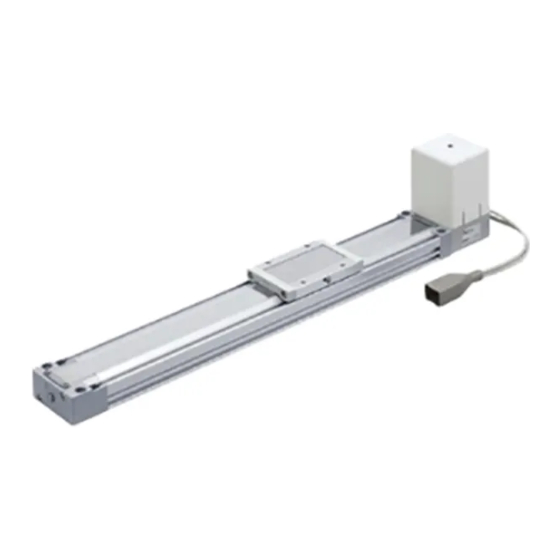
Electric actuator / slider type, ball screw type, belt drive
Hide thumbs
Also See for LEF Series:
- Operation manual (50 pages) ,
- Instruction manual (3 pages) ,
- Operation manual (45 pages)
Table of Contents
Advertisement
Quick Links
Advertisement
Table of Contents

Subscribe to Our Youtube Channel
Related Manuals for SMC Networks LEF Series


Summary of Contents for SMC Networks LEF Series
- Page 1 Doc.No. LEF-MM01601-A Maintenance Manual Product Name Electric Actuator / Slider Type Model / Series / Product Number LEFS/LEFB Series LEFS Series LEFB Series (Ball screw type) (Belt drive) Products after parts replacement by the user are outside of warranty.
- Page 2 Track changes Rev. Date of Approved Person in Details of the changes Remarks symbol change charge T.Sugiyama H.Shiomi 2016/03/23 First edition 2016/03/23 2016/03/23 T.Sugiyama T.Nakazawa 2016/06/16 Addition of grease part number. 2016/06/20 2016/06/16...
-
Page 3: Table Of Contents
Contents 1. Maintenance Precautions ..........- 2 - 2. Mounting and removal of the dust seal band and seal band stopper assembly ................- 3 - 3. Applying additional grease on the guide......- 4 - 4. Replenishment of grease for the ball screw ..... - 5 - 5. -
Page 4: Maintenance Precautions
1. Maintenance Precautions Warning 1) Remove the workpiece and disconnect the power supply during maintenance and replacement of the product. [Maintenance frequency] Preform maintenance according to the table below. if there are any problems, please contact SMC. Inspection frequency Appearance check Internal check Belt check Inspect daily before operating... -
Page 5: Mounting And Removal Of The Dust Seal Band And Seal Band Stopper Assembly
2.) If no locking adhesive is applied to the bolts or screws, take a countermeasure against loosening. 3) Refer to the spare parts list in the separate sheet for the part numbers and details of the spare parts. Japanese version: LEF-MM01101, LEF-MM01201 English version: LEF-MM01301, LEF-MM01401 4). -
Page 6: Applying Additional Grease On The Guide
2-3. Pull out the dust seal band to the opposite side of the motor. Dust seal band Direction to pull the dust seal band to remove 2-4. To put the dust seal band back, mount the dust seal band in reversed order of 2-1 to 2-3. For the replacement of the dust seal band and seal band stopper assembly, order replacement parts referring to the spare parts list in the attachment. -
Page 7: Replenishment Of Grease For The Ball Screw
4. Replenishment of grease for the ball screw Applicable model: LEFS 4-1. Remove the dust seal band. ( Refer to Chapter 2 Mounting and removal of the dust seal band and seal band stopper assembly) 4-2. Apply grease to the entire ball screw shaft using a spatula. Slowly slide the table by hand so that the grease is applied to the inside of the ball screw nut. - Page 8 Step motor (Servo/ 24VDC) / Servo motor (24VDC), LEFB25 AC servo motor With the dust seal band removed as in Chapter 2 Mounting and removal of the dust seal band and seal band stopper assembly, loosen the screw(2) which retains (3) pulley holder assembly, and then rotate (1)tension adjusting screw.
-
Page 9: Mounting/ Removal Of The Motor And Peripheral Equipments
Table.5-2 Data required for setting the tension meter that are recommended to tension the belt. Set values for acoustic belt tension Measurement Recommended meter position of the Model belt tension [N] WEIGHT table WIDTH SPAN +/-10% (∗) (L) [mm] [mm] [mm] LEFB16∗T LEFB25∗T... - Page 10 Parallel motor mounting type (without lock) (6) Insert something flat such as a cable tie behind the fingers of the motor cover to lift the fingers. Finger Parallel motor mounting type (with lock) (6) Lift the fingers of the motor cover to remove the cover. Referring to the removal procedure of 6-2-2, remove the motor.
- Page 11 6-1-2. AC Servo Motor Remove the screw(1). Hold the grommet(4) while removing the end cover(2) from the grommet downward. Remove the motor cover (3), and remove the grommet from the cable (5). Table.6-2 Motor cover fixing screws Tightening Screw Part to be tightened Model torque +/- Type...
- Page 12 6-2-1. Inline motor mouning type LEFS16/25 Step motor (Servo/ 24VDC) and servo motor (24VDC) Remove the screw (9) and motor assembly(10). Remove the screw(11) and motor(13) from the motor mount(12). Motor with lock. ∗ Do not loosen the screw connecting the motor and the lock.
- Page 13 Table.6-4 Motor assembly fixing screws Screw Part to be Tightening torque Models tightened +/- 10% [Nm] Type Size Qty. M4x12 LEFS∗32∗∗-∗ M4x55 LEFS∗32∗-∗B M4x12 LEFS∗40∗-∗ (9) Hexagon (13) LEFS∗40∗-∗B socket head cap M4x55 Motor LEFS∗25(S/T/V) ∗∗-∗ screw M4x12 LEFS∗32(S/T/V) ∗∗-∗ M5x15 LEFS∗40(S/T/V) ∗∗-∗...
- Page 14 AC Servo Motor Remove the screws (14). Then, remove the cover plate (15) and loosen the screws to detention the belt (16), and then remove the belt. Then, remove the screws (9) to remove the motor assembly (18). Remove the screws (19) and then, remove the motor (21) from the motor adapter (20).
- Page 15 6-3. To fit the belt back, mount the belt in reversed order of 6-1 to 6-2. Points to be Noted for Assembly Caution 1): For LEFS inline motor type, before tightening the screw (9), move the table after temporarily tightening the screw (9) and confirm that the motor can rotates smoothly.
- Page 16 Set the belt tension tool (25) to the pulley (24). Then, place the nozzle at the end of the plunger (26) to the plate. LEFS∗16, 25∗(L/R) LEFS∗32, 40*(L/R) Place the motor and the table as the drawing below, and then tighten the plunger until the end of the plunger or the nut contact the plate.
-
Page 17: Mounting/ Removal Of The Motor And Peripheral Equipments (Belt Type)
Adjustment using tensile force Pull the base of the motor with a cord or a long cable tie. With tensile force adjusted (Table.6-7), tighten the screws which secure the motor. Tension adjustment example Tensile force Table.6-7 Replacement Belt part No. and tensile force Tensile Size Replacement Belt part No. - Page 18 Table.7-1 Motor cover fixing screws Screw Part to be Tightening torque Models tightened +/- 10% [Nm] Type Size Qty. LEFB16∗T-∗ M3x70 LEFB16∗T-∗B M3x120 M3x85 LEFB25T-∗ M3x130 LEFB25T-∗B (1) Cross recessed (2) End cover 0.32 round head screw M3x70 LEFB25SAT-∗ M3x110 LEFB25AT-∗B M3x100 LEFB32T-∗...
- Page 19 7-2. Remove the motor. Caution) When the motor of AC servo type is replaced, Encoder Z-phase detecting position is changed inevitably. (Max. 1 lead) Adjust the home position shift distance according to the actual machine, in case of using Z-phase for home position rerurn. If encoder Z-phase detecting position must not be changed, actuator should be repaired in SMC factory.
- Page 20 Table.7-3 Motor assembly fixing screws Screw Part to be Tightening torque Models tightened +/- 10% [Nm] Type Size Qty. M2.6x20 LEFB16T-∗ 0.36 LEFB16AT-∗ M2.5x20 M3x35 0.63 LEFB25∗T-∗ LEFB32T-∗ M4x12 (9) Motor (8) Hexagon socket assembly head cap screw M4x55 LEFB32T-∗B LEFB25∗(S/T/V)∗S-∗∗...
-
Page 21: Mounting/ Removal Of The Belt (Belt Type)
8. Mounting/ removal of the Belt (Belt type) Applicable model: LEFB 8-1. With the dust seal band and motor are removed, remove the table cap (1) on the table. Then, remove the retaining screws of the belt holder assembly (2). (Refer to the Chapter 7 for the removal of the dust seal band and motor) Table.8-1 Belt holder assembly fixing screws Screw... - Page 22 LEFB32, 40∗(S/T/V)∗S Pull out the belt holder assembly (4) from the table (3). After loosening the hexagon socket head cap screw (7), remove the end block assembly (8) from the body in the direction of the arrow. Remove 2 cross recessed round head screws (5) to pull out the belt (6) downward.
- Page 23 Stopper Pulley holder assembly fixing bolt Stoppe Pulley Fig.8-1 Sectional view of the pulley holder LEFB32, 40∗(S/T/V)∗S Remove cross recessed countersunk head screws (11) holding the belt stopper assembly diagonally to remove the belt stopper assembly (12). Loop the belt around the end side pulley (13), then the motor side pulley (14) to hold the belt to the belt holder.
- Page 24 Motor side Table.8-3 Belt stopper assembly fixing screws Tightening Screw Part to be Model torque +/- tightened Type Size Qty. 10% [Nm] LEFB25∗(S/T/V)∗S (12) Belt stopper (11) Cross recessed LEFB32∗(S/T/V)∗S M3x8 0.32 assembly countersunk head screw LEFB40∗(S/T/V)∗S Note 2) Mount both ends of the belt in the loop shape to the belt holder. Engage five belt teeth each at both ends of the belt holder.
-
Page 25: Mounting/ Removal Of The Hub (Pulley) At The Motor Side
9. Mounting/ removal of the hub (pulley) at the motor side Applicable model: LEFS/LEFB 9-1. Remove the motor side hub (pulley) from the motor. Step motor (Servo/ 24VDC) and servo motor (24VDC) (1) Loosen the retaining screw (2) of the hub (pulley) (1), then remove the hub (pulley) from the motor (3). - Page 26 9-2. To reassemble, mount the hub in reversed order of removing. Points to be Noted for Assembly. Cautions 1): Step motor (Servo /24VDC) and servo motor (24VDC) When mounting the hub to the motor, make sure that the retaining screw of the hub becomes the right angle for the D-cut of the motor shaft.
-
Page 27: Mounting/ Removal Of The Housing
10.Mounting/ removal of the Housing Applicable model: LEFS/LEFB 10-1. Remove the housing. LEFS Loosen the round head combination screw (1), and then remove the screws (2), and the housing (3) and sliding bearing (4). ∗ Adhesive is applied. Contact SMC when screws cannot be loosened. Band stopper Dust seal band LEFB16, 25, 32∗T, LEFB25∗(S/T/V)∗S... - Page 28 Table.10-1 Fixing screws of the housing (end cover) and band stopper Screw Part to be Tightening torque Model tightened +/- 10% [Nm] Type Size Qty. LEFS∗16 M3x10 0.63 M4x12 LEFS∗25 M5x14 LEFS∗32 (2) Cross recessed round (3) Housing LEFS∗40 M6x16 head screw LEFB16 M3x10...
- Page 29 4-14-1, Sotokanda, Chiyoda-ku, Tokyo 101-0021 JAPAN Tel: + 81 3 5207 8249 Fax: +81 3 5298 5362 http://www.smcworld.com NOTE: Specifications are subject to change without prior notice and any obligation on the part of the manufacturer. © 2016 SMC Corporation All Rights Reserved - 27 -...
- Page 30 LEFS Spare parts list No. LEF-MM01301 Name Order number Applicable actuator model Contents Remarks LEFS-MC16 LEFS16**-* LEFS-MC16-B LEFS16**-*B LEFS-MC25 LEFS25**-* LEFS-MC25-B LEFS25**-*B LEFS-MC32 LEFS32*-* LEFS-MC32-B LEFS32*-*B LEFS-MC40 LEFS40*-* Motor cover, Grommet, End cover、Mounting [Tightening torque] 0.32N・m bolts LEFS-MC40-B LEFS40*-*B LEFS-MC25S LEFS25S*S-* LEFS-MC25S-B LEFS25S*S-*B Motor cover LEFS-MC32S LEFS32S*S-* Ass'y...
- Page 31 LEFB Spare parts list No. LEF-MM01401 Name Order number Applicable actuator model Contents Remarks LEFB-B16-* LEFB16*T-* [Pulling force] 30N LEFB-B25-* LEFB25*T-* [Pulling force] 45N LEFB-B32-* LEFB32*T-* [Pulling force] 75N Belt Belt LEFB-B25S-* LEFB25S*S-* [Pulling force] 82N LEFB-B32S-* LEFB32S*S-* [Pulling force] 136N LEFB-B40S-* LEFB40S*S-* [Pulling force] 186N LEFB-DS16-* LEFB16*T-* LEFB-DS25-*...
Need help?
Do you have a question about the LEF Series and is the answer not in the manual?
Questions and answers