Advertisement
Quick Links
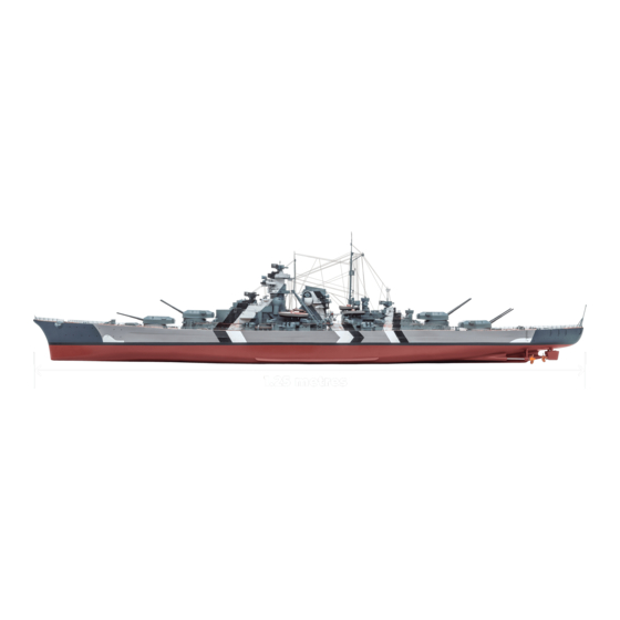
Pack 06 | Build Instructions
Your 1:200 scale model of the legendary battleship Bismarck is packed with
intricate details which precisely replicate every aspect of this state-of-the-
art warship. Each piece has been created using premium quality materials to
bring maximum enjoyment during your complete build.
STAGE 57: THE FIRST 15CM TURRET AND
A CIRCUIT BOARD
STAGE 58: MOTOR FOR THE FIRST 15CM
TURRET
STAGE 59: THE NEXT HULL SECTION
STAGE 60: THE NEXT HULL SECTION
STAGE 61: SECOND 15CM GUN TURRET
AND THE FUNNEL
STAGE 62: THE MOTOR FOR THE SECOND
15CM GUN TURRET
© 2020 Hachette Partworks Ltd.
North America Edition by Agora Models
In your sixth model pack, you will assemble:
STAGE 63: TWO SEARCHLIGHTS FOR THE
FUNNEL
STAGE 64: THE NEXT SECTION OF THE UPPER
DECK
STAGE 65: TWO MORE SEARCHLIGHTS
STAGE 66: THE NEXT SECTION OF THE HULL
STAGE 67: THE THIRD 15CM GUN TURRET
STAGE 68: THE NEXT SECTION OF THE HULL
Advertisement

Related Manuals for Agora Models Bismarck 06


Summary of Contents for Agora Models Bismarck 06
- Page 1 STAGE 61: SECOND 15CM GUN TURRET STAGE 67: THE THIRD 15CM GUN TURRET AND THE FUNNEL STAGE 68: THE NEXT SECTION OF THE HULL STAGE 62: THE MOTOR FOR THE SECOND 15CM GUN TURRET © 2020 Hachette Partworks Ltd. North America Edition by Agora Models...
- Page 2 Advice from the experts Spare screws are included with each part. Occasionally, you may be instructed to keep spare or unused screws for a later stage. Keep these spares in a safe place and label them correctly. Please make sure you don’t mix up the screws. They look quite similar, but the threads do vary slightly.
- Page 3 STAGE 57 THE FIRST 15CM TURRET AND A CIRCUIT BOARD 57-01 57-02 57-03 57-05 57-04 57-06 2 x 5 57-09 57-08 57-07 1.7 x 6 COMPONENTS CHECKLIST 57-01: 57-05: 57-08: Gun turret housing (Port I) Two artillery target finders Cable label (A1) and six searchlight 57-02: 15cm gun barrels with...
- Page 4 29-02 29-02 57-05 Cut the six searchlight directors from frame Glue the remaining three searchlight directors Fix three to the port side of the superstructure, gluing place in the recesses on the starboard side of decking 29-02 29-02 them into the recesses in decking as shown.
- Page 5 40-03 38-02 Repeat to fix the second antenna outrigger to the Fit the support to the underside of the foretop 40-03 38-02 underside of the searchlight platform on the gallery so that the straight edge of the tapered port side. sides is flush with the underside of the gallery, as shown.
- Page 6 . ASSEMBLING AND FITTING THE FIRST 15CM GUN TURRET 2 x 5 57-01 57-02 57-03 57-01 57-01 57-03 Turn the gun turret housing upside down and Fit the base of the turret over the housing. Fix 57-02 insert the gun barrels through the two in place with a single 2 x 5mm screw.
- Page 7 . TESTING THE MOTORS AND LIGHTS 34-02 37-02 First, we test the two radar units, 34-02 37-02 . In order to do this, connect the 4-07 4-06 battery box to the circuit board B-18 Plug the cable marked into the free B-18 4-06 socket on the circuit board...
- Page 8 STAGE 58 MOTOR FOR THE FIRST 15CM TURRET 58-01 58-02 58-04 58-05 58-03 COMPONENTS CHECKLIST 58-01: Motor (controls the 58-03: 58-05: Cable label rotation of the gun) 58-04: Motor housing Three 2 x 5mm PB screws 58-02: Cable for the motor .
- Page 9 Fit the unmarked end of the connector 58-02 on cable into the socket of the 58-01 58-01 motor as shown. 58-02 58-03 Fit the drive cog onto the shaft 58-01 of the motor with the ribs of the cog away from the motor, as shown. The cog is quite a loose fit on the shaft of the motor.
- Page 10 58-04 Fit the housing over the motor 58-01 so that the screw holes in the 58-04 housing are aligned with the sockets in the upper deck, as shown. 58-01 Fix the housing in place with two screws. 58-04 58-01 Completed work The motor that controls rotation of the first 15cm gun turret has been fitted to the underside of the upper deck.
- Page 11 STAGE 59 THE NEXT HULL SECTION 59-01 59-03 59-02 COMPONENTS CHECKLIST 59-01: Lower port hull 59-02: Mooring 59-03: Framework Four 2 x 4 PM section manoeuvre light screws ADDING DETAILS TO THE FORWARD SUPERSTRUCTURE 59-02 37-02 43-08 (1) 59-03 59-02 59-03 Remove part from the frame.
- Page 12 FITTING THE NEXT HULL SECTION Place the hull assembly on your work 59-01 surface. Take the lower port hull section 59-01 and fit it in place so that the raised screw sockets fit into the sockets on 46-01 56-01 parts as shown.
- Page 13 STAGE 60 THE NEXT HULL SECTION 60-01 60-02 COMPONENTS CHECKLIST 60-01: Starboard lower hull section Four 2 x 4mm PM screws 60-02: Platform (parts A, B, C and D) . SHAPING AND ASSEMBLING THE PLATFORM Cut the platform part from the 60-02 frame .
- Page 14 60-02 Cut the railing part from frame Note the position of the sloping corner of the railing (circled). Apply a little superglue to the three pegs at the bottom of the railing and fit them into the holes in the platform part .
- Page 15 . FITTING THE HULL SECTION Take the hull assembly and identify the 60-01 position for hull section . Two raised screw sockets fit under the 49-01 56-01 sockets on part and one fits under 49-01 the socket on part 60-01 56-01 When you are happy with the fit, fix in 60-01...
- Page 16 STAGE 61 SECOND 15CM GUN TURRET AND THE FUNNEL 61-01 61-04 61-02 61-03 61-06 61-05 61-07 61-09 61-08 1.7 x 6 2 x 5 COMPONENTS CHECKLIST 61-01: Gun turret housing 61-04: 61-08: Cable and switch (starboard I) 61-05: 61-09: Right half of the funnel Cable label 61-02: 15cm gun barrels with...
- Page 17 61-03 61-01 1.7 x 6 22-02 61-04 22-01 19-01/22-01/48- Take the large upper deck assembly Holding the gun turret in place, carefully turn the deck 61-04 . Identify and position of the gun turret assembly on assembly over. Fit the cog on the base plate 22-02 61-03...
- Page 18 . ASSEMBLING A PLATFORM AND THE FUNNEL 61-07 60-07 Cut the platform section from the frame Cut the platform railing D from the frame Bend the railing up at right angles. Bend the two Apply a little superglue to the three pegs along the short edges up at right angles, as indicated by the bottom of the railing and fix them into the three holes arrows.
- Page 19 STAGE 62 THE MOTOR FOR THE SECOND 15CM GUN TURRET 62-01 62-02 62-03 COMPONENTS CHECKLIST 62-01: Motor (controls the 62-02: Cable for the motor rotation of the gun) 62-03: Cable label ATTACHING THE CABLE TO THE MOTOR 62-02 Take the cable and remove the wire wrapped around it as shown.
- Page 20 62-03 Take the cable label and remove the backing. Wrap the label around the cable, close to one of the connectors. 62-02 (The connectors are identical.) 62-03 Fit the connector on the other end of 62-02 cable into the socket in the motor 62-01 62-01 62-02...
- Page 21 STAGE 63 TWO SEARCHLIGHTS FOR THE FUNNEL 63-05 63-03 63-02 63-04 63-01 63-08 63-06 63-07 63-12 63-10 63-11 63-09 63-13 COMPONENTS CHECKLIST 63-01: 63-06: 63-11: Grille Two LED cables 63-02: Base plate 63-07: Cover 63-12: Cable label 63-03: 63-08: 63-13: Deck covering Searchlight parts (2x A–F) Cable label...
- Page 22 22-01 62-01 63-07 63-07 63-07 62-01 63-07 Fit the cover over the motor , ensuring Fix the cover in place using two screws. that the screw holes on the cover align with those on Support the deck from below while tightening 22-01 the upper deck section the screws.
- Page 23 . ASSEMBLING THE SEARCHLIGHTS 63-13 63-11 63-12 63-09 63-11 Cut the searchlight body from one of the frames Take the two LED cables and the cable labels 63-08 63-09 63-12 63-13 . Fit one of the searchlight lenses into . Wrap a label around each of the part as indicated by the red arrow (and inset).
- Page 24 Apply a little superglue to the peg on the searchlight Glue the searchlight base to the underside of the base and fix it into the recess in the centre of the searchlight stand (inset). Repeat this section of support arm (see arrow).
- Page 25 61-06 61-05 63-11 63-11 63-11 63-11 Pass the starboard searchlight cable through Pass the port searchlight cable through the slot 61-05 61-06 the slot in the funnel section in the funnel section 63-11 63-05 38-02 63-11 63-10 63-10 Gently pull the two cables through the slot, bringing Cut the first frame from part .
- Page 26 STAGE 64 THE NEXT SECTION OF THE UPPER DECK 64-02 64-01 COMPONENTS CHECKLIST 64-01: The sixth section of the upper 64-02: Two 15cm gun barbettes deck . FITTING THE FIFTH AND SIXTH 15CM GUN BARBETTES 64-02 64-02 64-01 64-02 64-01 Place the upper deck section and the two This photo shows the correct positioning of the first...
- Page 27 64-02 Fit the second barbette on the 64-01 64-01 other side of the deck , as shown. 64-02 This shows the underside of the deck 64-01 . The tabs on the barbettes fit into the recesses around the openings 64-02 in the deck.
- Page 28 STAGE 65 TWO MORE SEARCHLIGHTS 65-01 65-03 65-02 65-04 65-05 65-06 65-08 65-07 65-09 COMPONENTS CHECKLIST 65-01: Forward searchlight 65-04: Funnel extension 65-08: Cable label (B-12) platform 65-05: 65-09: Searchlight parts Cable label (B-13) 65-02: Port protective hood (2 x A – F) 65-03: 65-06: Starboard protective...
- Page 29 65-06 65-07 65-07 Cut the searchlight body from one of the frames Fit the LED on cable into the back of the 65-05 65-06 65-05 . Fit one of the searchlight lenses into searchlight, part from frame . Study the part as indicated by the red arrow (inset).
- Page 30 Apply a little superglue to the peg on the searchlight Slide the searchlight base up the cable to the stand and fix it into the recess in the centre of the underside of the searchlight stand . Glue the base support arm in place, as shown.
- Page 31 65-09 65-01 65-01 65-08 65-01 65-08 Take the forward searchlight platform and the Fit the searchlight with cable marking (B-12) on 65-09 65-01 cable with label marking (B-13). Fit the the other side of the searchlight platform in the searchlight on the platform over the slot on the same way, as shown.
- Page 32 Take the starboard protective hood 65-03 and, as before, check the fit over the starboard searchlight. Apply a little superglue to fix in place. 65-03 65-01 This shows the port and starboard 65-02 65-03 protective hoods, 65-02 viewed from the front of the funnel. 65-03 65-01 Completed work...
- Page 33 STAGE 66 THE NEXT SECTION OF THE HULL 66-01 66-02 COMPONENTS CHECKLIST 66-01: Upper port hull section Five 2 x 4mm PM screws 66-02: Connector . ASSEMBLING THE NEXT HULL SECTION 66-01 66-01 59-01 59-01 66-01 59-01 Place the hull assembly on you work surface. Position Fix the upper left hull section to part 66-01...
- Page 34 66-02 Fit the connector across the join 66-01 52-01 between hull sections 52-01 66-02 so that the screw sockets on part 66-01 66-02 fit over the raised screw sockets on parts 66-01 52-01 66-02 Fix the connector in place with screws, as shown.
- Page 35 STAGE 67 THE THIRD 15CM GUN TURRET 67-01 67-02 67-03 67-04 67-08 67-05 67-06 67-07 PB 1.7 x 6 2 x 5 COMPONENTS CHECKLIST 67-01: 15cm gun housing 67-05: Left rangefinder hood (BBII – second port turret) 67-06: Right rangefinder hood Two 2 x 5mm PB screws 67-02: Gun turret base plate...
- Page 36 67-01 67-01 67-06 67-03 67-06 67-01 Glue the right rangefinder hood to the gun Turn the gun housing over and insert the gun 67-01 67-03 housing as shown. barrels so that the pegs of the cradle rest in the recesses of the tabs in the housing (arrows). 67-02 2 x 5 67-02...
- Page 37 . FITTING THE SWITCH 67-08 Wrap the cable label around 67-08 67-07 cable near the connector (inset). 67-07 Take the switch and fit it in the recess on the underside of upper deck 67-07 48-01 section 67-07 48-01 67-07 Fix the switch in place with a screw, as shown.
- Page 38 STAGE 68 THE NEXT SECTION OF THE HULL 68-01 68-02 COMPONENTS CHECKLIST 68-01: Upper starboard 68-02: Connecting five 2 x 4mm hull section piece PM screws FITTING THE HULL SECTION 68-01 Check the fit of hull section . The tabs with screw holes on the lower edge fit over the screw sockets in part 68-01 60-01...
- Page 39 Fix the upper starboard hull section 68-01 in place with two screws, as shown. 68-01 60-01 68-02 Use the connector to join hull 68-01 54-01 section to hull section , so 54-01 68-01 68-02 that the screw sockets in part over the raised screw sockets in the hull sections.
Need help?
Do you have a question about the Bismarck 06 and is the answer not in the manual?
Questions and answers