
Related Manuals for CENTURION SYSTEMS INTERCOM HANDSET


Summary of Contents for CENTURION SYSTEMS INTERCOM HANDSET
- Page 1 AUDIO INTERCOM SYSTEMS INTERCOM HANDSET INSTALLATION MANUAL Centurion Systems (Pty) Ltd www.centsys.com...
- Page 2 Saturdays 08h00 to 14h00 GMT+2 Centurion Systems (Pty) Ltd reserves the right to make changes to the product described in this manual without notice and without obligation to notify any persons of any such revisions or changes. Additionally, Centurion Systems (Pty) Ltd makes no representations or warranties with respect to this manual.
-
Page 3: Table Of Contents
Page 12 5.1. Entry Panel Installation Page 12 5.1.1. Wall-mounted Installation Page 12 5.1.2. Gooseneck Installation Page 12 5.2. Intercom HANDSET Installation Page 16 WIRING Page 20 6.1. Requirements for 12V DC Operators Page 21 6.2. Requirements for 24V DC Operators Page 21 6.3. -
Page 4: Introduction
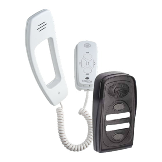
INTRODUCTION 1. Introduction The INTERCOM HANDSET is a very versatile intercom system designed for a multitude of applications ranging from a basic 1 to 1 kit to larger installations with up to five components in the system. A component is either an entry panel or a handset as detailed below. - Page 5 SECTION 1 INTRODUCTION Other features Using the same two wire bus, each handset can independently operate the door lock or gate motor linked to each entry panel. The entry panel is provided with a potential-free, normally- open contact to operate either a gate motor or, in series with a separate power supply, to activate a door lock.
-
Page 6: Important Safety Information
SECTION 1 INTRODUCTION 1.1. Important Safety Information ATTENTION! To ensure the safety of people and possessions, it is important that you read all of the following instructions. Incorrect installation or incorrect use of the product could cause serious harm to people. The installer, being either professional or DIY, is the last person on the site who can ensure that the operator is safely installed and that the whole system can be operated safely. - Page 7 Never short-circuit the battery and do not attempt to recharge the batteries with power supply units other than that supplied with the product, or manufactured by Centurion Systems (Pty) Ltd Safety devices must be fitted to the installation to guard against mechanical movement risks such as crushing, dragging and shearing •...
-
Page 8: Specifications
SECTION 2 SPECIFICATIONS 2. Specifications 2.1. Physical Dimensions 40mm 30mm 64mm 53mm FIGURE 2. INTERCOM HANDSET PHYSICAL DIMENSIONS 36mm 74mm FIGURE 3. CALL MODULE PHYSICAL DIMENSIONS page 8 www.centsys.com... -
Page 9: Technical Specifications
SECTION 2 SPECIFICATIONS 2.2. Technical Specifications Supply Voltage Range 12-14V DC (14V DC if powering handset) Current Draw Quiescent 150mA (+/- 60mA for a 1:1 system) Maximum 200mA Speech Volume Adjustable at each entry panel and handset Two polarized wires for speech, call and Wiring / Cabling gate/door lock release Electronic while button is depressed,... -
Page 10: Product Identification
11. Entry Panel Label 1 Intercom Handset 12. Trigger Button (Entry Panel 1) Intercom Handset Cradle 13. Auxillary Button Intercom Handset Cradle Mounting Plate 14. Gate Status LED Entry Panel Front Speaker 15. Trigger Button (Entry Panel 2) Entry Panel Button 1 16. -
Page 11: Required Tools And Equipment
SECTION 4 REQUIRED TOOLS AND EQUIPMENT 4. Required Tools and Equipment Hammer Screwdrivers 6mm Phillips Connector 3.5mm Flat block Electric Drill Pin punch Crimping tool and Pin lugs Angle grinder Measuring tape Masonry drill bits Welding machine Hacksaw (including consumables) and safety equipment Safety equipment (goggles, gloves, etc.) -
Page 12: Installation
SECTION 5 INSTALLATION 5. Installation 5.1. Entry Panel Installation 5.1.1. Wall-mount Installation Position entry panel on wall adjacent to entrance gate or door. Mount at a height that allows for comfortably speaking into the microphone. A recommended height is shown in Figure 6. - Page 13 SECTION 5 INSTALLATION Entry Panel Front Fascia Lift the Front Fascia of the Entry Panel off. Entry Panel FIGURE 9 Flat Screwdriver Insert a Flat Screwdriver into the groove as shown in Figure 10, and unclip the Electronic Module from Entry Panel Base Plate.
- Page 14 SECTION 5 INSTALLATION Hold the Entry Panel Base against the wall at the required height ensuring that it is vertical and mark the location of the mounting holes. Using a 6mm masonry bit, drill holes into the wall for the rawlplugs provided in the kit. If the cable is being routed into the unit from a concealed conduit behind the base, knock out one of the cable entry holes provided in the base and feed through the cable.
- Page 15 SECTION 5 INSTALLATION Entry Panel Base Plate Lens INSTALLATION Write the Call Button Labels, insert them back into the Lens(es) and clip Mr. X the Lens(es) back into the Chassis Mr. Y Call Button Label FIGURE 15 Entry Panel Entry Panel Base Plate Front Fascia Clip the Entry Panel Front Fascia...
-
Page 16: Intercom Handset Installation
SECTION 5 INSTALLATION 5.2. Intercom Handset Installation Position the Intercom Handset on wall where required at a height that will allow for comfortable use of the Intercom Handset. A height of 1550mm from the floor to the base of the cradle is recommended. - Page 17 SECTION 5 INSTALLATION Craft Knife In the case of an uneven wall, the tabs may be cut as Cradle Base shown in Figure 21 to allow Back Plate the Cradle Base to ‘sit’ on Tab on the back of the wall without rocking. the Cradle Base Back Plate Craft...
- Page 18 SECTION 5 INSTALLATION Cable Tie Route the cable over the channel in the Cradle Base cross bar. Using the Cable coming Cable Tie provided, secure the cable from conduit in wall to the Cradle Base Back Plate as shown in Figure 23. Tighten cable tie ensuring that there is sufficient slack to terminate the cable onto the electronics (±80mm).
- Page 19 SECTION 5 INSTALLATION Clip the Cradle back onto the Cradle Cradle Base Plate. Cover It will be necessary when commissioning the unit to have the Front Cover removed. Cradle Base Back Plate FIGURE 26 Clip the long tail end of the telephone cord into the jack provided at the bottom of the Cradle and similarly into the Handset.
-
Page 20: Wiring
6. Wiring Power Supply The INTERCOM HANDSET operates off a 14V DC supply. The system is designed so that power can be connected to any one of the components in the system. If the system is being installed with a gate operator that can provide at least a 12V DC 150mA supply, the entry panel can be connected directly to this unit. -
Page 21: Requirements For 12V Dc Operators
SECTION 6 WIRING 6.1. Requirements for 12V DC Operators Additional wiring required for Auxiliary and Status LED +12VDC -12VDC Two-wire Bus FIGURE 28. WIRING REQUIREMENTS FOR 12V DC OPERATORS 6.2. Requirements for 24V DC Operators Additional wiring required for Auxiliary and Status LED Two-wire Bus +12V DC Out -12V DC Out... -
Page 22: Door Lock Drive
SECTION 6 WIRING 6.3. Door Lock Drive ENTRY PANEL Lock Power Supply FIGURE 30 6.4. Wiring the Gate Status LED HANDSET Gate Operator CRADLE Control Card Status Terminal For SMART Opererators, wire "*" into any of the output termianls that is configured to Gate Status (IO4 is defaulted to "Gate Status") Ground... -
Page 23: Full Site Wiring Diagram (12V Dc Operators)
SECTION 6 WIRING 6.5. Full Site Wiring Diagram (12V DC Operators) Gate Operator HANDSET Control Card CRADLE Status Terminal For SMART Opererators, wire "*" into any of the output terminals that is configured Ground to Gate Status (IO4 is defaulted to "Gate Status") HANDSET 1. -
Page 24: Full Site Wiring Diagram (12V Dc Operators)
SECTION 6 WIRING 6.6. Full Site Wiring Diagram (24V DC Operators) 24VDC SMART Dx Control Card HANDSET CRADLE +24VDC Out Trigger (Default) Ground Status (Default) HANDSET CRADLE 1. Only one 12V DC Power Supply is typically needed to power the system. 2. -
Page 25: Intercom Switch Wiring
FIGURE 34 • Two-wire bus with secure signal to operate gate Connect power to the INTERCOM HANDSET via the INTERCOM switch. • There is no need to take battery power to the entry panel • An alternative solution is to wire TRG and COM to the Aux terminals on the handset PCB page 25 www.centsys.com... -
Page 26: Completing The Installation
SECTION 7 COMPLETING THE INSTALLATION 7. Completing the Installation 7.1. Group and Volume Settings 7.1.1. Entry Panel and Selector Switch • If the system has only one Entry Panel set the Selector Switch to the upper position • If there are two Entry Panels set the Selector Switch on the one Panel to the upper position and on the other Panel to the lower position •... -
Page 27: Checking Functions
SECTION 8 FAULT FINDING GUIDE 7.2. Checking Functions Press the Gate/Door Release pushbutton on each HANDSET and check that the Gate/Door adjacent to each entry panel operates correctly. 8. Fault-finding Guide At each HANDSET press the pushbutton to call the handsets in the other group. •... -
Page 28: Warranty Information
4. Has been repaired by any workshop and / or person NOT previously authorised by the manufacturer. 5. Has been repaired with components not previously tested, passed or authorised by Centurion Systems (Pty) Ltd, South Africa or one of its subsidiary companies. page 28 www.centsys.com... - Page 29 Notes page 29 www.centsys.com...
- Page 30 Notes page 30 www.centsys.com...
- Page 31 Notes page 31 www.centsys.com...
- Page 32 The CENTURION and CENTSYS logos, all product and brand names in this document that are accompanied by the TM symbol are trademarks of Centurion Systems (Pty) Ltd, in South Africa and other territories; all rights are reserved. We invite you to contact us for further details.
Need help?
Do you have a question about the INTERCOM HANDSET and is the answer not in the manual?
Questions and answers