Advertisement
Quick Links
X3 ENVIRONMENTAL DATA LOGGER
QUICK START GUIDE
IMPORTANT - BEFORE FIELD DEPLOYMENT: Completely configure new X3 systems with sensors and a telemetry con-
nection in a nearby work area. Operate the system for several hours and verify correct sensor readings. Use this test run
to become familiar with the system's features and functions, setting the stage for a successful deployment.
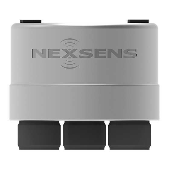
Figure 1: X3 Environmental Data Logger
Overview
The X3 Environmental Data Logger with Cellular
Telemetry includes an integrated modem and external
antenna. Three sensor ports provide industry-standard
protocols including SDI-12, RS-232, and RS-485. The
center 6-pin port offers direct communication (serial to
PC) and power input.
Users can configure the X3 Data Logger for deployment
using a USB adapter and the CONNECT software. Data
is accessed and stored on the WQData LIVE web data
center. An easy-to-use dashboard and built-in sensor
library automatically facilitate setup and configuration.
What's Included
• (1) X3 Environmental Data Logger
• (2) Buoy mounting kits (small and large buoy kits)
• (3) Sensor port plugs, spare orings
• (1) Power port plug, spare oring
• (1) Oring grease tube
• (1) Cellular antenna
• (1) Quick Start Guide
Note: Applications scientists and engineers at
NexSens will pre-program data loggers based on user
specifications. In many instances, the system will be
ready for "plug-and-play" and will not require the
subsequent Data Logger Setup steps below to be
performed. If a system is pre-programmed, a System
Integration Guide will be included with the order,
providing an overview of the following steps to get the
system up and running.
Review the System Integration Guide guide and
skip to the WQData LIVE Setup section. Note: It is
recommended to download the CONNECT software
(step 1) for future use.
Data Logger Setup
Download the CONNECT software and establish a
1
connection with the logger via the direct connect
USB cable (UW6-USB-485P-DC).
a. nexsens.com/connst
b. The middle 6-pin port on the X3 is for providing
power and communication through the CONNECT
software.
Figure 2: Middle 6-pin power and communication port.
Review the sensor integration guides on the
2
NexSens knowledge base to prepare the sensor(s)
for programming.
a. nexsens.com/sensorskb
b. If a guide is unavailable, follow the links in step 3 to
determine if a script for the sensor is available or if a
new script must be created.
Advertisement

Summary of Contents for NexSens X3
- Page 1 QUICK START GUIDE IMPORTANT - BEFORE FIELD DEPLOYMENT: Completely configure new X3 systems with sensors and a telemetry con- nection in a nearby work area. Operate the system for several hours and verify correct sensor readings. Use this test run to become familiar with the system's features and functions, setting the stage for a successful deployment.
- Page 2 PROJECTS from the drop-down menu. If there are any questions, contact NexSens technical In the project, go to ADMIN | Settings. support for assistance with new or existing scripts: a. Choose the Project/Site drop-down menu and then Phone: 937-426-2151;...
- Page 3 Use a 1/2" socket to tighten. All X3 data loggers will come with an active SIM card. If cellular service is purchased through NexSens, the card can be used for the duration of the active plan. If cellular service is not purchased through NexSens, the SIM card will be active for a three-month trial period.
- Page 4 For any connectors within or below the solar tower, it is best to tie a rope around each connector to pull them through the opening at the top of the solar tower. Figure 10: Cellular antenna installation. 937-426-2703 2091 Exchange Court www.nexsens.com Fairborn, Ohio 45324...


Need help?
Do you have a question about the X3 and is the answer not in the manual?
Questions and answers