
Related Manuals for NexSens X2-CB


Summary of Contents for NexSens X2-CB
- Page 1 X2-CB Buoy-Mounted Data Logger User Guide Last Revision: 16 March 2023 Date Generated: 16 March 2023 Copyright © 2023 NexSens Technology, Inc.
-
Page 2: Table Of Contents
Radio to PC Cellular Set up a 4G Cellular Account for an X2 Data Logger Install a SIM Card into an X2-CB/X2-CBMC Cellular Logger Set an X2 Data Logger APN Using CONNECT Iridium Setup Gmail Account to Allow WQData LIVE Access (Iridium) - Page 3 Check an Antenna Connection on an X2-CB Component Overview Verify a Connection is Tight Inspect the RF Connectors for Moisture Access a Main or RTU SD Card in an X2-CB Data Logger Tools Required Open the X2-CB Data Logger Access the RTU SD Card...
- Page 4 Access the Main SD Card Reassemble the X2-CB Housing X2 Storage Requirements 5. Warranty 6. Service Request Service Request...
-
Page 5: System Power
CB-Series solar towers have a special UW-6 plug with a jumper built in that completes the circuit for the battery to supply power to the X2-CB data logger. The X2-CB will not receive power unless the solar panel is connected to the COM/SOLAR port. -
Page 6: Basic Requirements
Supply Voltage: 5-24VDC [+/-15%] Operating Current Max: 300mA Peak Current: 500mA for 1 second (@ 12V) All standard CB-Series buoys meet and exceed the X2-CB required specifications. Connector Wiring Solar power is supplied to the CB-Series battery pack via the UW-6 Receptacle (marked ‘COM/SOLAR‘) port, which also acts as a power switch between the battery and data logger. -
Page 7: Power & Communications Accessories
The schematic below shows the CB-Series buoy wiring from top to bottom. Figure 4: X2-CB power schematic. Power & Communications Accessories Please visit the accessories tab on the X2-CB product page to purchase power/comms accessories. CB-PW-AC-30W: CB-Series battery float charger, 30W... -
Page 8: Uw-6 Universal Pinout
UW-6 Universal Pinout The schematics and table below detail the 6-pin plug and receptacle (UW-6) universal pinout for all 6-pin NexSens cables excluding the 6-pin AC adapter. Figure 1: NexSens UW-6 receptacle pinout Figure 2: NexSens UW-6 plug pinout Figure 3: X2-CBMC/SDLMC MCIL-6-FS 6-pin... - Page 9 Note: For instruments shown below, all signals in the table refer to their 6-pin receptacle port. Plug Pin Receptacle Pin Wire Color G2-Series Signal X2 Signal X2-CB Buoy Solar Signal** Ext. Power Input Main Power Input X2 PCB Power In Yellow — Secondary Pwr Input*...
-
Page 10: Buzzer Indicator
Buzzer Indicator X2-SDL & X2-CB data loggers are equipped with an onboard buzzer to provide audible system status feedback to the user. X2-SDL/X2-CB Buzzer Indicator Status Lookup Event Beep Type Status When power is applied Short beep System boot successful... -
Page 11: Performing A Measurement System Power Budget
To aid with this, NexSens has developed a power budget tool which can quickly estimate the expected power performance of systems using the most common NexSens buoy platforms, data logger configurations, and commonly integrated NexSens and third-party sensors for deployment locations throughout the world. - Page 12 The example below shows an Airmar 200WX-IPX7 weather station, NexSens T-Node FR temperature string with 10 nodes, Nortek Signature 1000 current profiler, and a YSI EXO3 sonde all on switch power. Select sensors from drop-down list.
- Page 13 b. While the pre-populated sensor list is fairly extensive and frequently updated, there may be cases where a sensor is not listed. In such cases, it is possible to enter up to four devices manually by selecting Custom 1/2/3/4 from the drop-down list. Custom sensor entry.
- Page 14 c. Once selected, proceed to the Custom User Entry tab of the spreadsheet. Navigate to the Sensor Details section and fill in the prompted information either using data from the device manufacturer or measured data during device testing. Custom sensor data entry.
- Page 15 However, if an appropriate location does not appear to be available, it is recommended to contact NexSens as new locations can normally be added quickly upon request.
-
Page 17: Advanced Custom User Entry
Advanced Custom User Entry Because flexibility for use with user-supplied loggers, batteries, sensors and other electronics is a basic design principle of NexSens CB-Series data buoys, the power budget calculator also facilitates user entry of data for all components. Besides just the Custom sensor data entry noted in step 3 above, the Custom User Entry tab supports input of user-supplied data loggers, solar panels, telemetry systems and battery packs, as well as solar insolation for the exact deployment location. -
Page 18: Disclaimer
Disclaimer The NexSens power budget calculator is intended as a helping tool for correct system design. It integrates efficiency factors and other conservative estimates of power consumption in order to provide a best possible approximation of system power performance and viability. However, real-world conditions may vary, and field testing is the only way to ensure that a system will perform adequately. -
Page 19: Establish Communication
2. Establish Communication X2 Data Flow The X2 is designed to provide real-time data to users, most commonly via the WQData LIVE web datacenter. The diagrams below outline how the data travels from sensor to user. Wi-Fi Figure 1: X2 to WQData LIVE. -
Page 20: Cellular
Cellular Figure 2: X2-C to WQData LIVE. -
Page 21: Iridium
Iridium Figure 3: X2-I to WQData LIVE. -
Page 22: Radio To Cellular
Radio to Cellular Figure 4: X2-RC to WQData LIVE. -
Page 23: Radio To Pc
Radio to PC Figure 5: X2-R to WQData LIVE. Notes: Data is posted to WQData LIVE’s secure MySQL database using HTTP POST protocol Data is transmitted in XML format... -
Page 24: Cellular
Set up a 4G Cellular Account for an X2 Data Logger While NexSens can provision and manage a Verizon cellular account for an X2 Data Logger if desired, it may be preferred to set up and manage an account directly with a provider. -
Page 26: Install A Sim Card Into An X2-Cb/X2-Cbmc Cellular Logger
Install a SIM Card into an X2-CB/X2-CBMC Cellular Logger While it is always recommended that a SIM card be sent to NexSens for installation prior to shipment, in some cases it may be necessary for an end user to install a SIM card. - Page 27 2. [For CB-150/250/450 buoys only] Use a 9/16″ socket wrench to remove the (6) bolts holding the buoy’s solar tower to access the data well. Figure 4: Remove solar tower from CB- 150/250/450 buoys. 3. Remove the (8) bolts from the X2-CB/X2-CBMC using a 9/16″ socket wrench.
- Page 28 Figure 5: X2-CB removal from CB-150/250/450 Figure 6: X2-CB removal from CB-650/950/1250 buoys. buoys. 4. Lift up the logger and disconnect the 6-pin plug connecting the battery harness to the bottom cable of the X2 logger. Figure 7: Unplug X2-CB in CB-150/250/450 Figure 8: Unplug X2-CB in CB-650/950/1250 buoys.
- Page 29 Figure 10: Disconnect the Molex power connector. 7. Locate the SIM slot tray on the cell modem. NexSens provides two distinct modem models within an X2 data logger. a. Devices sold within the United States, and certain international shipments, will have an AT&T, Verizon, or NA4G modem outlined in the schematic on the left...
- Page 30 Figure 11: AT&T, Verizon, & NA4G modem Figure 12: CAT-M modem schematic. schematic. 8. For each modem model, orient the modems as shown below and follow the arrows to unlock and open the SIM card tray.
- Page 31 Figure 13: Open the AT&T, Verizon, or NA4G Figure 14: Open the CAT-M modem SIM card modem SIM card tray. tray. 9. Slide the SIM into the tray such that the indentation on the card will align with the same indentation on the holder when closed.
- Page 32 Figure 15: Insert the 2FF size (25mm x 15mm) Figure 16: Insert the 4FF size (12.3mm x SIM card into the AT&T, Verizon, or NA4G 8.8mm) into the CAT-M modem. modem. 10. Gently swing the tray closed and press forward gently to lock it back into place.
- Page 33 Figure 18: Close the CAT-M modem SIM tray. modem SIM tray. 11. Realign the O-ring within the grooves on the bottom of the X2-CB/X2-CBMC enclosure. a. Place the desiccant on the RTU board next to the modem. b. Orient the X2-CB/X2-CBMC enclosure such that the power cable feeding up through...
- Page 34 Figure 19: Re-align the O-ring and ensure to Figure 20: Reconnect the Molex power cable. replace the desiccant. 12. Align the holes on the enclosure with the threads on the plate. Ensure the large exterior O-ring is secure in its grooves and is making proper contact with the bottom of the logger plate.
- Page 35 If the SIM card ID is not read, open the logger enclosure and re-position the SIM card. 14. Place the re-assembled X2-CB/X2-CBMC back on top of the data well. a. Make sure the primary O-ring is clear of debris and centered in the groove.
- Page 36 Ensure there are no substantial gaps between the data logger plate and the metal frame of the buoy data well. Figure 25: Bolt down the logger in a crisscross Figure 24: Bolt down the X2-CB/X2-CBMC. pattern. 16. Re-install the solar tower and move the buoy outside. Power on the logger using the solar tower plug and gather multiple hours of readings to ensure the primary power is increasing while the buoy is in direct sunlight.
-
Page 37: Set An X2 Data Logger Apn Using Connect
Set an X2 Data Logger APN Using CONNECT Users who have sourced their own mobile data accounts and installed a SIM card will need to configure the associated APN in the X2 logger using the CONNECT software. Power Up RTU Connect the X2 logger to a PC and launch the CONNECT software. - Page 38 3. Select Turn Power ON to startup the X2’s RTU. a. Note that this process may take up to 30 seconds to complete (15-sec typical). b. The RTU will power down every 10 minutes and will require the RTU power to be turned on again.
- Page 39 Verify Current APN Settings 1. To confirm the active APN settings, select and send the AT+CGDCONT? command from the Direct Command list. Figure 3: Response to AT+CGDCONT? command displaying the modem’s currently configured APN profiles. 2. Depending on the model of cellular X2, the system will actively use either the APN setting profiles on the modem.
- Page 40 Figure 4: Pre-selected APN list. b. If the required APN is not on the list, which will often be the case, enter the proper APN enclosed in quotations. Figure 5: Example of setting a custom APN on a 4G Verizon X2. 4.
- Page 41 2. Read the Signal Quality of the system to verify it is within the -51 dBm to -90 dBm range. Figure 7: Verify the signal strength is adequate. 3. Send either the AT#SGACT=1,1 (for AT&T/International) or AT#SGACT=3,1 (for Verizon) direct commands to query the modem to connect to the network and resolve an IP address.
- Page 42 Figure 9: Modem successfully pinged WQData LIVE. Additional Features Modem Firmware Switch Command (For LE910C1-NF Modems) The LE910C1-NF modem has the ability to switch between Verizon and AT&T modes with a single command. Toggle by entering the following commands in the Direct Command section: 1.
- Page 43 b. AT#FWSWITCH=0,1 (AT&T/International) At this point, complete the update by cycling power (turn off and on) the modem. Figure 12: Change from Verizon to AT&T/International mode.
- Page 44 The ME90G1-WW worldwide modem contains two SIM card holders. If cellular service is purchased through NexSens, a SIM will be inserted into the SIM holder 0 slot, which is active by default. However, if cellular service is not purchased through NexSens, a SIM will be inserted into the SIM holder 1 slot as a backup.
- Page 45 active SIM card holder. AT#SIMDET=0 An “OK” response should occur after each command. 3. To switch from SIM holder 0 to SIM holder 1, send: AT#GPIO=8,1,1,1 The SIM holder slot 1 is now the active slot. 4. Enable the active SIM card holder by sending: AT#SIMDET=1 SIM holder 1 is enabled.
-
Page 46: Iridium
The data messages are then downloaded from the email server to the WQData LIVE web datacenter. In order to facilitate this process, NexSens hosts a secure Gmail account as a medium to store and upload data to WQData LIVE. Although this option is freely available to all customers that purchase an Iridium system from NexSens, private Gmail accounts can be set up to achieve the same purpose. - Page 47 4. Use the keypad icon at the top right of the screen to open the Google account settings. Click on Account. Figure 2: Google account. 5. Choose Security. Figure 3: Google Security tab. 6. Scroll down to Signing in to Google. Change the 2-step verification to on.
- Page 48 Figure 4: Enable 2-step verification. 7. Select App Passwords and under Select app choose Other (custom name). In the space provided enter wqdatalive. Figure 5: Enter wqdatalive and click Generate. 8. Click Generate. A new app password should appear. Copy and save this password to a separate location.
- Page 49 Figure 6: Generated app password. 9. Insert this app password into the Iridium account information on WQData LIVE while configuring the X2 logger. a. Note: Do not include the spaces shown in the password. b. If the Iridium system was setup previously, all Iridium information entered previously should remain the same, while the password will now be entered as the new generated app password.
-
Page 50: Setup Iridium (Sbd) Data Account
All Iridium-enabled X2 data loggers must have an active SBD (short-burst data) account in order to send measurement data to WQData LIVE. While NexSens Technology can configure and manage Iridium (SBD) data account plans, users may prefer to set up their own data services. - Page 51 1. Request setup of a new SBD account. 2. Provide the Iridium modem IMEI number for each X2 logger. a. NexSens will supply this after assigning the X2 loggers. 3. Provide the anticipated monthy data usage estimate for plan selection.
- Page 52 4. Provide an email account that will receive the data messages from the system. a. NexSens strongly recommends assigning a new, dedicated email account for this purpose. b. A standard Gmail account will suffice, click here for configuration instructions. c. Having the data sent to a second mailbox address is recommended.
-
Page 53: Setup Iridium Logger Through Connect
Establish logger connection Note: Ensure the data logger receives 12VDC power from either the internal batteries on a NexSens buoy system or the AC power adapter from a NexSens UW6-USB-485P-DC cable. 4. For new systems (i.e., no prior sensor detection), the data logger will automatically begin a sensor detection based on its default enabled scripts. - Page 54 3. Re-apply 12VDC power and listen for the audible beeps or view the LEDs depending on the X2 logger model. X2 Pole Mount LED Indicators X2-CB/X2-SDL Buzzer Pattern Indicator If receiving insufficient signal strength, move the logger into an area devoid of overhead obstructions.
- Page 55 request messages from that email and begin processing the X2’s sensor configuration. Once processing is complete, the X2’s sensors and parameter list will be visible on WQData LIVE. Update Logger’s Binary Format 1. Once the configuration is visible, the user must send the “Update Binary Format” command from WQData LIVE.
- Page 56 Dashboard. Figure 1: ADMIN | Settings tab. 3. Click on the Advanced Device Remote Configuration drop-down menu and choose the logger. Enter code ‘nexsens’ when prompted. Figure 2: Advanced Device Remote Configuration drop- down menu. 4. Click the UPDATE button underneath Update Binary Format.
-
Page 57: Iridium Transmission Delay
Iridium Transmission Delay Compared to data loggers utilizing cellular, radio, or Wi-Fi telemetry, Iridium transmission systems have an additional step in the data upload process which may cause a delay in the time it takes from the logger recording a measurement to data being posted on WQData LIVE. - Page 58 Figure 1: Iridium X2 data flow.
-
Page 59: Radio
Radio Set Up a NexSens Radio Network Each XBEE radio module that ships with a NexSens radio X2 has a unique identifier. Both the base and field nodes use this identifier to establish connections throughout the radio network. All field radios in the network must have the identifier information for the base station as a destination for their logged data. - Page 60 Figure 1: Discover available radios. Figure 2: Radio communication settings.
- Page 61 4. Click the plus icon to the left of the magnifying glass to actively search for the Digi radio device using the previously set communication settings. Figure 3: Add the base radio module. 5. The Digi Base Radio station should soon appear in the Radio Modules list.
- Page 62 Figure 4: Digi Base Radio detection. Establish Connection with the X2 Base Station 1. Power on the NexSens base station, then click the Link icon next to the Digi Base Radio module to search for the NexSens base station.
- Page 63 Figure 5: Digi base radio search for NexSens base station.
- Page 64 2. Once the NexSens base station is found, select Add selected devices at the bottom of the interface. Figure 6: NexSens base station found. 3. Open the NexSens base radio settings by selecting the NexSens base station (Example: X2-RC-DG-01300) under the list of radio modules.
- Page 65 Figure 8: NexSens base radio unique serial number. 5. After copying the information, power down the NexSens base station and apply power to all the field radios. Click the Link icon next to the Digi Base Radio module to search for the nodes.
- Page 66 Figure 10: Read the field radio settings. 3. After the settings are completely loaded, scroll down to the Addressing section and insert the identifier copied previously into the DH Destination Address High and DL Destination Address Low. a. Write the new destination to the device by selecting the pencil icon next to the parameter.
- Page 67 4. Power on all of the field nodes first, and then power on the base station. a. This provides adequate time for the field radio nodes to start transmitting their signal to the base station. b. Once all of the field nodes have been found, they will display in the Radio Settings. Figure 13: Successful radio detection of node 01326.
-
Page 68: Connect Sensors
NexSens to check compatibility. X2-SDL X2-CB X2 Environmental Data X2-SDL Submersible Data X2-CB Buoy-Mounted Data Logger Logger Logger Tier 1 Sensors These sensors will be automatically detected by the X2. If multiple sensors are connected to the same logger, they must be addressed uniquely. The interface used by the sensors is bolded above each model. - Page 69 Analog Analog RS-485 SDI-12 RS-232 Kipp & Zonen Li-COR Underwater and NexSens T-Node Pro-Oceanus Solu-Blu Pyranometers Terrestrial PAR Sensors FR/TS210 Temperature Observator ANALITE Dissolved C02 Sensor Strings NEP5000 [Turbidity] SDI-12 SDI-12 or RS-232 SDI-12 SDI-12 SDI-12 Sea-Bird Scientific Seametrics CT2X...
-
Page 70: Tier 2 Sensors
Tier 2 Sensors These sensors require limited setup prior to connection. The scope of setup varies by sensor type but typically includes setting up a template, configuring the device or selecting the parameter output. These tasks are often done with a separate PC program provided by the sensor manufacturer. -
Page 71: Tier 3 Sensors
These sensors are not commonly supported by the X2, but can be added through the creation of a user-defined script. The script is written in Lua and utilizes NexSens-created functions to simplify programming. As long as the sensor communicates using SDI-12, RS- 485, or RS-232 and can be powered from a 12V supply, it should be compatible with the X2. - Page 72 SDI-12 SDI-12 RS-232 RS-232 RS-485 GSI Sontek YSI H-3401 Turner Designs C3 Turner Designs C6P YSI ODO Dissolved Argonaut-XR Tipping Submersible Submersible Oxygen Sensor Current Bucket Rain Fluorometer Fluorometer Profiler Gauge...
-
Page 73: Connect Software
User-generated generic scripts are possible to create using the CONNECT software; however, it is recommended to contact NexSens before creating a script. Click the logo below to link to the CONNECT software section of the NexSens Knowledge Base to download and learn about CONNECT. -
Page 74: Uw Connectors
UW Connectors UW-8 Sensor Port Pinout NexSens X2 and G2-Series data loggers incorporate UW-8 receptacles for connection of sensor cables with UW-8 plug connectors. The pinout for the UW-8 data logger sensor ports is as follows: Figure 1: NexSens X2/G2 data logger 8-pin (UW-8) sensor port pinout. -
Page 75: Uw-8 Plug Pinout
CON). This ensures that all signal wires are connected to the appropriate pins, and the connectors are sealed with epoxy to provide fully waterproof connections. While this is critical for use on buoys (X2-CB, X2-SDL data loggers) and in other wet environments, users may in some cases choose to install UW Field Wireable Plugs (part number UW-FWP). -
Page 76: X2 Sensor Detection
X2 Sensor Detection Traditionally, complex programming software is required to configure an environmental data logger. The user must indicate the communication protocols, sensor addresses, measurement commands, data format, and power requirements of all connected sensors. Contrarily, X2 data loggers use sensor detection to simplify the programming requirements for environmental measurement systems. -
Page 77: Setup In Wqdata Live
Setup in WQData LIVE Creating a WQData LIVE Project Data loggers and measurement data are organized into Projects on WQData LIVE. Projects may contain one or more Sites for further organization, and each Site may contain one or more data loggers. To create a Project: 1. - Page 78 4. Fill out the fields in the corresponding menu to title the Project, and then click CREATE PROJECT. Figure 3: Create Project interface. 5. The main project Dashboard will appear. Create and name a Site within the new project as desired by going to Admin | Settings at the top, then to the Project/Site tab and selecting New Site.
- Page 79 7. Click SAVE when finished.
-
Page 80: Adding A Data Logger To A Wqdata Live Project
Adding a Data Logger to a WQData LIVE Project During first-time configuration, data loggers are added to WQData LIVE Projects using a Claim Code supplied with each data logger. To assign a data logger using a Claim Code: 1. Log in to WQData LIVE and find the username in the top right hand corner of the page. Mouse over the username to reveal a drop down menu and click PROJECTS. - Page 81 3. After selecting or creating a Project, click on the ADMIN tab and then Settings located at the top of the dashboard. Figure 3: Navigate to ADMIN | Settings at the top of the project dashboard. 4. Click on the gray bar that says Project/Site to open a drop-down menu. Choose Sites to open a second drop-down menu.
- Page 82 6. Add a new logger by entering the Claim Code in the field near the bottom of the Sites menu. Then click Add Device. a. Locate the Claim Code on the serial label attached to the data logger’s Quick Start Guide.
-
Page 83: Changing Sensor Log Intervals
Note: Certain sensors take multiple minutes to record and process a reading. Contact NexSens to verify the maximum recommended sampling frequency of a device before increasing its frequency. Figure 1: Enter desired log interval changes into the New Value field for each sensor. -
Page 84: Changing Data Logger Transmission Interval
Changing Data Logger Transmission Interval The Transmit Interval in the Device Remote Configuration Tool determines how often a data logger will power up its telemetry modem to contact the WQData LIVE web datacenter. On each transmission, the data logger will: Upload all newly logged data. -
Page 85: Run Remote Sensor Detection
Run Remote Sensor Detection WQData LIVE can run a remote sensor detection on an X2 data logger without the need to connect with a configuration cable. Before proceeding, reference the X2 Sensor Detection overview and the Auto-Detection Troubleshooting guide. The detection process will permanently alter the X2 data logger programming. - Page 86 4. Click SAVE , then complete the confirmation prompt to submit the command for processing. a. Prior to submitting the sensor detection command, double-check that all considerations laid out in the Sensor Detection Troubleshooting guide have been met. Figure 3: Sensor detection confirmation prompt.
-
Page 87: X2 Logger Diagnostic Readings
To avoid data logging interruptions, it is recommended an X2 be sent to NexSens Technology to replace the RTC battery when it falls to 2.7V or below. 3. Primary Power – Each X2 is capable of utilizing two independent power inputs for redundancy. - Page 88 a. 12V-15V for SP-Series solar power pack or CB-Series buoys. b. Consistent 12.1-12.5V for an AC power adapter. c. 8.5V to 12.9V for an SBP500 battery pack, depending on how recently the installed D-cell batteries were replaced. *If none of these supplies are connected and a secondary power source is used, primary power will consequently read ~0V.
- Page 89 Acceptable values will range from a slight negative percentage (effectively zero) up to ~50%. If a logger reports humidity greater than 50%, replace the desiccant bag inside X2-CB and inspect the enclosure seal. High humidity can contribute to telemetry problems and, in more extreme cases, damage the logger circuitry as a result.
- Page 90 Expected values are given in the following: 1. Cellular systems a. -51 to -79 dBm for strong signal strength (~4-5 bars equivalent) b. -80 to -89 dBm for moderate signal strength (2-3 bars equivalent) c. -90 to -99 dBm for weak signal strength (1-2 bar equivalent) d.
- Page 91 Iridium satellite, and Wi-Fi. Values of zero indicate that no errors were observed. If status errors appear frequently and subsequently affect data transmissions, contact NexSens Technology for troubleshooting assistance. Supply the status error code reported by the logger.
-
Page 92: Troubleshooting And Maintenance
Old SLA-type batteries, or those that have fallen to a voltage that is too low, may be unable to output the system current required for detection. Once all of the above have been verified, re-run sensor detection. Contact NexSens Technology for further assistance if the sensor still is not identified. -
Page 93: Running A Sensor Re-Detection
WQData LIVE. CONNECT will display the final sensor configuration that the user should confirm before transmitting the new sensor configuration. NexSens also recommends removing the antenna from the device to avoid automatically sending a new configuration to the web. -
Page 94: Confirming The New Sensor Configuration
A new location is necessary to avoid overwriting the original device configuration, which may cause incorrect sensor/parameter labeling and create parsing issues on the web. A NexSens support specialist will walk you through this process, rename the old device, and ensure the new device is reading correctly. - Page 95 If the user only adds sensors/parameters, these will be added to the end of the configuration, and the user can update without a NexSens support specialist. In that instance, the user should do the following: 1. Reconnect the antenna to the data logger.
-
Page 96: Verify Battery Voltage Of A Cb-Series Buoy
Measure the voltage between pins 3 (V+) and 4 (GND) on the SOLAR port. Healthy SLA battery voltage is 12.0-14.9V. Figure 1: UW-6 SOLAR port receptacle pinout for X2-CB data loggers and CB-PTL pass-through lids. SLA batteries which have fallen below ~10V... -
Page 97: Replace A Battery In A Cb-Series Data Buoy
New desiccant (recommended) Data Well Lid Removal 1. Disconnect the 6-pin solar panel cable from the X2-CB’s SOLAR port to remove power to the data logger. a. Cover the plug and receptacle to prevent moisture and debris from the port pins and O-rings. -
Page 98: Battery Removal
1. Lift the buoy plate off of the data well. Disconnect the 6-pin UW-plug running between the solar regulator and the X2-CB and protect the connectors. a. This will expose the data well where the battery and solar regulator are installed. - Page 99 Figure 4: Unplug X2-CB in CB-150/250/450 Figure 5: Unplug X2-CB in CB-650/950/1250 buoys. buoys. 2. Remove the foam coverings to expose the battery harness. 3. Remove the two nut, lock washer and flat washer pairs securing the regulator bracket to the battery mount posts (threaded rod).
-
Page 100: New Battery Installation
New Battery Installation [For systems with a single battery] 1. Lower the new battery into the data well. a. It may be necessary to adjust the foam for a proper fit. 2. Skip ahead to Step 3 “For All Systems” [Only for systems with 2 or more batteries] 1. -
Page 101: Buoy Plate Re-Installation
Figure 6: Re-connect the data well 6-pin cable connection. 2. Align the X2-CB or pass-through plate with the mounting holes on the buoy and verify that the large O-ring is in good condition, clear of debris and lightly greased. 3. Reattach the plate using a 9/16″ socket wrench and the original set of bolts and lock... - Page 102 SOLAR port. This should read close to the voltage of the new battery (~12V to 15V). Figure 9: UW-6 SOLAR port receptacle pinout for X2-CB data loggers and CB-PTL pass-through lids. 6. Connect the 6-pin solar panel plug to the buoy’s SOLAR port to reapply power to the...
-
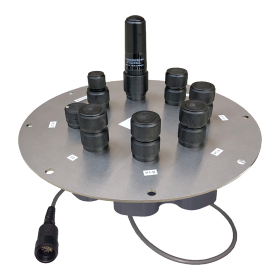
Page 104: Remove An X2/Isic-Cb For Repair
Remove an X2/iSIC-CB for repair If an X2-CB data logger needs to be sent in for evaluation or repair, please reference the following steps for removal: Figure 1: X2-CB data logger. Tools Required 9/16″ Socket Wrench Instructions 1. Disconnect the 6-pin solar panel or UW-6 USB cable from the X2-CB/X2-CBMC... - Page 105 Figure 2: X2-CB port configuration. Figure 3: X2-CBMC port configuration. 2. [For CB-150/250/450 buoys only] Use a 9/16″ socket wrench to remove the (6) bolts holding the buoy’s solar tower to access the data well. Figure 4: Remove solar tower from CB-...
- Page 106 Figure 8: Unplug X2-CB in CB-650/950/1250 buoys. buoys. 5. Pack with plenty of protective material and ship the X2/iSIC-CB to NexSens as directed by NexSens technical support. 6. For deployed systems, it will be necessary to protect the data well and system batteries while the logger is being evaluated.
- Page 107 Place the blank plate over the top of the data well and align the holes. b. Re-install the (8) bolts with lock washers from the X2-CB or data well pass-through plate using a 9/16″ socket wrench, tightening them evenly in a cross pattern to ensure an even O-ring seal.
-
Page 108: Replace Desiccant
Replace Desiccant Each X2-CB/X2-CBMC ships with a bag of desiccant inside the logger enclosure. This desiccant bag should be replaced whenever: 1. The X2-CB/CBMC enclosure is opened. 2. The Internal Humidity diagnostic parameter reads 50% or greater. Figure 1: X2-CB data logger. - Page 109 2. [For CB-150/250/450 buoys only] Use a 9/16″ socket wrench to remove the (6) bolts holding the buoy’s solar tower to access the data well. Figure 5: Remove solar tower from CB- 150/250/450 buoys. 3. Remove the (8) bolts from the X2-CB/X2-CBMC using a 9/16″ socket wrench.
- Page 110 Figure 6: X2-CB removal from CB-150/250/450 Figure 7: X2-CB removal from CB-650/950/1250 buoys. buoys. 4. Lift up the logger and disconnect the 6-pin plug connecting the battery harness to the bottom cable of the X2 logger. Figure 8: Unplug X2-CB in CB-150/250/450 Figure 9: Unplug X2-CB in CB-650/950/1250 buoys.
-
Page 111: Replace The Desiccant And Re-Assemble The X2-Cb Housing
Replace the desiccant and re-assemble the X2-CB Housing 1. Realign the O-ring within the grooves on the bottom of the X2-CB/X2-CBMC enclosure. a. Place the desiccant on the RTU board next to the modem. b. Orient the X2-CB/X2-CBMC enclosure such that the power cable feeding up through... - Page 112 Figure 12: Re-align the O-ring and ensure to Figure 13: Reconnect the Molex power cable. replace the desiccant. 2. Align the holes on the enclosure with the threads on the plate. Ensure the large exterior O-ring is secure in its grooves and is making proper contact with the bottom of the logger plate.
- Page 113 3. Place the re-assembled X2-CB/X2-CBMC back on top of the data well. a. Ensure the primary O-ring is clear of debris and centered in the groove. It is recommended to replace the desiccant pack within the data well at this time.
- Page 114 Ensure there are no substantial gaps between the data logger plate and the metal frame of the buoy data well. Figure 18: Bolt down the logger in a crisscross Figure 17: Bolt down the X2-CB/X2-CBMC. pattern.
-
Page 115: Check An Antenna Connection On An
Check an Antenna Connection on an X2-CB The telemetry antenna for cellular or radio X2-CB loggers threads onto a dedicated RF connector port on top of the CB-plate. It may be necessary to inspect the condition of the RF connection if signal strength or connection reliability issues are encountered in the field. -
Page 116: Inspect The Rf Connectors For Moisture
Tighten antenna bushing to plate port. Inspect the RF Connectors for Moisture 1. Grab the bushing of the antenna and turn the assembly counterclockwise to remove it. Rotate the antenna bushing counterclockwise to remove the antenna. Antenna and bushing removed from CB-plate. 2. - Page 117 Verify Antenna O-ring is intact and seated properly. 3. Inspect the RF connector of the antenna and verify there are no signs of moisture, corrosion or coaxial contact damage. a. If moisture is visible, use canned air to dry it out. Verify the antenna’s RF connector is free from moisture, corrosion, or...
- Page 118 Verify the CB-plate RF port is dry and clean. 5. Rethread the bushing back on the antenna, double-checking the antenna O-ring stays seated. Verify the connection is hand-tight. Thread the bushing back onto the antenna. Turn the bushing-to-antenna connection until hand-tight. 6.
-
Page 119: Access A Main Or Rtu Sd Card In An X2-Cb Data Logger
Access a Main or RTU SD Card in an X2-CB Data Logger While it is always recommended that the data logger be sent to NexSens for an SD card installation or replacement, in some cases, it may be necessary for an end user to install an SD card. - Page 120 2. [For CB-150/250/450 buoys only] Use a 9/16″ socket wrench to remove the (6) bolts holding the buoy’s solar tower to access the data well. Figure 4: Remove solar tower from CB- 150/250/450 buoys. 3. Remove the (8) bolts from the X2-CB/X2-CBMC using a 9/16″ socket wrench.
- Page 121 Figure 5: X2-CB removal from CB-150/250/450 Figure 6: X2-CB removal from CB-650/950/1250 buoys. buoys. 4. Lift up the logger and disconnect the 6-pin plug connecting the battery harness to the bottom cable of the X2 logger. Figure 7: Unplug X2-CB in CB-150/250/450 Figure 8: Unplug X2-CB in CB-650/950/1250 buoys.
-
Page 122: Access The Rtu Sd Card
Figure 10: Disconnect the Molex power connector. Access the RTU SD Card 1. Locate the Buoy P2-B JST port on the X2-CB expansion PCB. The SD card slot for the RTU is located directly above it on the underside of the topmost-facing PCB. - Page 123 Figure 11: RTU SD card location. 2. Press the SD card inward towards its mount to unlock it. After successful disengagement, remove the card (using tweezers as necessary) from the slot. 3. After making the proper adjustments to the SD card, re-insert it into the same location. Access the Main SD Card 1.
- Page 124 4. After making the proper adjustments to the SD card, re-insert it into the same location. Reassemble the X2-CB Housing 1. Realign the O-ring within the grooves on the bottom of the X2-CB/X2-CBMC enclosure. a. Place the desiccant on the RTU board next to the modem.
- Page 125 3. Place the re-assembled X2-CB/X2-CBMC back on top of the data well. a. Ensure the primary O-ring is clear of debris and centered in the groove. It is recommended to replace the desiccant pack within the data well at this time.
- Page 126 Ensure there are no substantial gaps between the data logger plate and the metal frame of the buoy data well. Figure 19: Bolt down the logger in a crisscross Figure 18: Bolt down the X2-CB/X2-CBMC. pattern. 5. Re-install the solar tower and move the buoy outside. Power on the logger using the solar tower plug and gather multiple hours of readings to ensure the primary power is increasing while the buoy is in direct sunlight.
- Page 127 X2 Storage Requirements The following practices should be carried out when storing an X2 data logger for an extended period of time: Disconnect the 6-pin SP-series solar power pack UW6-PW AC power adapter cable from the center port at the bottom of the X2. This removes power from the data logger and all connected sensors.
- Page 128 Limitation of Warranty This warranty is not applicable to any NexSens Technology, Inc. product damage or failure caused by failure to install, operate or use the product in accordance with NexSens Technology, Inc.
- Page 129 An email authorization receipt with reference number will be sent to print and include with your shipment. Products within the warranty period will be fixed at no charge. Initial evaluations are performed at no cost and a quote will be provided if charges apply. For additional support or inquiries, email support@nexsens.com.
Need help?
Do you have a question about the X2-CB and is the answer not in the manual?
Questions and answers