
Related Manuals for NexSens X2-SDL


Summary of Contents for NexSens X2-SDL
- Page 1 X2-SDL Submersible Data Logger User Guide Last Revision: 3 April 2023 Date Generated: 28 April 2023 Copyright © 2023 NexSens Technology, Inc.
-
Page 2: Table Of Contents
Table of Contents 1. General X2-SDL Body Tag Identification What depth of submersion is the X2-SDL rated for? 2. System Power What type of batteries does the X2-SDL take? Apply Power to the X2-SDL Basic Requirements Input Channels Connector Wiring... - Page 3 Running a Sensor Re-Detection Re-Detection Considerations Re-Detection Process Confirming the New Sensor Configuration Updating the Sensor Configuration on WQData LIVE At what voltage should batteries be replaced? Cycle Power X2-SDL O-ring Maintenance X2-SDL Storage Requirements 6. Warranty 7. Service Request Service Request...
-
Page 4: General
1. General X2-SDL Body Tag Identification Each X2-SDL and SDL-V2 data logger has a body tag number for identification. The long housing tube has the tag etched between the antenna and sensor bulkheads. The default name of the device on WQData LIVE will incorporate this number (see Figure 3). - Page 5 Figure 3: X2-SDL default device name. Note all SDLs will have a ‘3’ entered in front of the Body Tag number.
-
Page 6: What Depth Of Submersion Is The X2-Sdl Rated For
What depth of submersion is the X2-SDL rated for? The X2-SDL is rated for submersion up to 200ft (~60m) depth. Note that the SDL-CAP accessory is required to fully submerge cellular or radio models containing an external antenna. The antenna port of Wi-Fi only models is epoxied closed... -
Page 7: System Power
What type of batteries does the X2-SDL take? The X2-SDL requires (16) D-Cell Duracell Alkaline batteries. D-cell batteries from other manufacturers may have sub-flush negative terminals which can result in poor contact and may affect the consistency of power supplied to the X2-SDL logger. -
Page 8: Apply Power To The
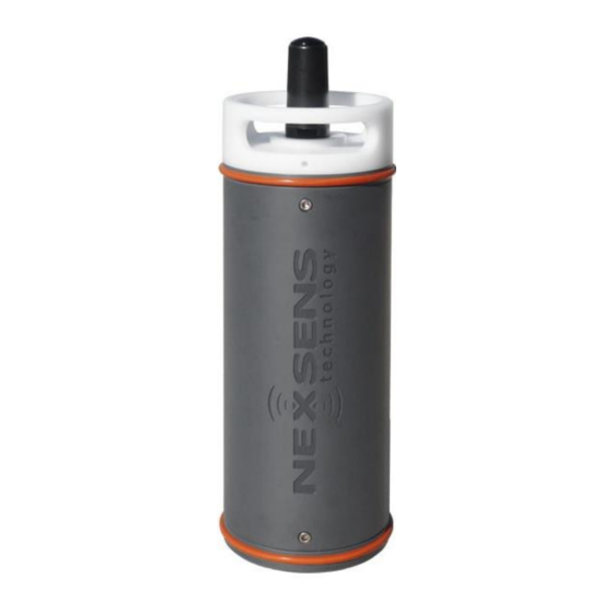
Apply Power to the X2-SDL The X2-SDL has flexible power input choices that provide several options in terms of type and number of power sources. Figure 1: X2-SDL Data Logger. Basic Requirements 5-24 VDC [+/-10%] (Reverse polarity protected) Current Draw (Typical @ 12VDC): Low power sleep: 350uA; Logger Active: 35mA; Wi-Fi Transmitting: 43mA;... -
Page 9: Connector Wiring
Install Batteries In an X2-SDL Data Logger Connector Wiring Power may be applied to the X2-SDL via the UW-6 receptacle port by a UW-USB-485P for connection to a PC, or from a customized solar power kit. Most applications, however, rely on the internal D-Cell Alkaline batteries during deployment. -
Page 10: Install Batteries In The X2-Sdl Data Logger
Note: Due to the double O-ring lid seal, this will take significant effort to loosen. b. The 3/16″ ball-point hex driver included in the X2-SDL maintenance kit can be inserted into either of the two recesses in the lid to provide extra leverage. - Page 11 D-cell batteries. Figure 2: Insert (16) D-cell batteries. 4. Thread the battery lid back on to the top bulkhead of the X2-SDL. 5. Rotate the lid clockwise and tighten securely using the hex driver. a. Once the large washer at the bottom of the white battery lid makes contact with...
-
Page 12: Universal Pinout
UW-6 Universal Pinout The schematics and table below detail the 6-pin plug and receptacle (UW-6) universal pinout for all 6-pin NexSens cables excluding the 6-pin AC adapter. Figure 1: NexSens UW-6 receptacle pinout Figure 2: NexSens UW-6 plug pinout Figure 3: X2-CBMC/SDLMC MCIL-6-FS 6-pin... - Page 13 RS-485 B RS-485 B RS-485 B Green RS-485 A RS-485 A RS-485 A iSIC-V2 X2-CB** G2-RAIN X2-SDL* X2-CBMC** *X2-SDL’s purchased after August 2021 do not include secondary power. **Wire colors for the X2- CB/X2-CBMC follow the UW-6 Bulk Pinout X2-SDLMC G2-EXO...
-
Page 14: Buzzer Indicator
Buzzer Indicator X2-SDL & X2-CB data loggers are equipped with an onboard buzzer indicator to provide audible system status feedback to the user. X2-SDL/X2-CB Buzzer Indicator Status Lookup Event Beep Type Status When power is applied Short beep System boot successful... -
Page 15: Performing A Measurement System Power Budget
To aid with this, NexSens has developed a power budget tool which can quickly estimate the expected power performance of systems using the most common NexSens buoy platforms, data logger configurations, and commonly integrated NexSens and third-party sensors for deployment locations throughout the world. - Page 16 The example below shows an Airmar 200WX-IPX7 weather station, NexSens T-Node FR temperature string with 10 nodes, Nortek Signature 1000 current profiler, and a YSI EXO3 sonde all on switch power. Figure 3: Select sensors from drop-down list.
- Page 17 b. While the pre-populated sensor list is fairly extensive and frequently updated, it does not list all compatible sensors. In such cases, it is possible to enter up to four devices manually by selecting Custom 1/2/3/4 from the drop-down list. Figure 4: Custom sensor entry.
- Page 18 c. Once selected, proceed to the Custom User Entry tab of the spreadsheet. Then, navigate to the Sensor Details section. Fill in the prompted information either using data from the device manufacturer or measured data during device testing. Figure 5: Custom sensor data entry.
- Page 19 Note that some instrument types have a number of different configurations which may affect power performance. The predefined sensors in the drop-down list reflect a typical configuration and information provided by the manufacturer or NexSens bench testing where applicable. These therefore represent a best approximation based on available information.
-
Page 21: Advanced Custom User Entry
Advanced Custom User Entry Because flexibility for use with user-supplied loggers, batteries, sensors and other electronics is a basic design principle of NexSens CB-Series data buoys, the power budget calculator also facilitates user entry of data for all components. Besides just the Custom sensor data entry noted in step 3 above, the Custom User Entry tab supports additional inputs. -
Page 22: Disclaimer
Disclaimer The NexSens power budget calculator serves as a helping tool for correct system design. It integrates efficiency factors and other conservative estimates of power consumption in order to provide a best possible approximation of system power performance and viability. -
Page 23: Establish Communication
3. Establish Communication X2 Data Flow The X2 is designed to provide real-time data to users, most commonly via the WQData LIVE web datacenter. The diagrams below outline how the data travels from sensor to user. Wi-Fi Figure 1: X2 to WQData LIVE. -
Page 24: Cellular
Cellular Figure 2: X2-C to WQData LIVE. -
Page 25: Iridium
Iridium Figure 3: X2-I to WQData LIVE. -
Page 26: Radio To Cellular
Radio to Cellular Figure 4: X2-RC to WQData LIVE. -
Page 27: Radio To Pc
Radio to PC Figure 5: X2-R to WQData LIVE. Notes: Data is posted to WQData LIVE’s secure MySQL database using HTTP POST protocol Data is transmitted in XML format... -
Page 28: Wi-Fi
Wi-Fi Configure Network Settings Wi-Fi only models of the X2 data logger can be configured to upload to the WQData LIVE datacenter over a local wireless network. To configure network settings: Establish a connection to the X2’s direct Wi-Fi network. 2. - Page 29 Figure 2: Network settings menu. 4. Toggle the Wi-Fi Mode to Network. 5. Enter the SSID, Security Type, and Password of the wireless network the data logger will be using. a. Proceed to step 6 if the X2 should automatically be assigned a network address via DHCP.
- Page 30 A prompt will appear requesting the X2 Wi-Fi to be reset by inserting a magnet into the lid. b. Cycling power (for X2-CB or X2-SDL models) will also accomplish this reset. 7. Disconnect the laptop or mobile device used to configure the logger from the X2’s...
- Page 31 a. An X2 cannot simultaneously connect to a mobile device and a local wireless network. Any mobile device connection to the X2 will prevent it from connecting to the local wireless network and contacting the WQData LIVE web datacenter. b. Due to the above, it is generally advisable to have the device ‘forget’ the X2’s network so that it does not auto-reconnect to it.
-
Page 32: Cellular
Set up a 4G Cellular Account for an X2 Data Logger While NexSens can provision and manage a Verizon cellular account for an X2 Data Logger if desired, it may be preferred to set up and manage an account directly with a provider. - Page 33 Figure 1: SIM card size schematic. Step 4) Mail SIM card to NexSens Technology for installation and X2 testing Send the SIM card for the X2 telemetry to NexSens for pre-shipment installation and testing (strongly recommended). Please ship the SIM card to:...
-
Page 34: Install A Sim Card
Note that two connections for the battery and RF antenna (on cellular models) will be connected to the main body and can be damaged if under tension. Removal of X2-SDL tube 3. Locate the SIM card slot and gently push the tray forwards to unlock it as indicated... - Page 35 SIM card slot 4. Swing the SIM tray open. Open tray on SIM card slot 5. Place the SIM in the tray such that the indentation on the card will align with the same indentation on the holder when closed. Insert SIM card 6.
- Page 36 Make sure no wiring is pinched when the tube is re-installed. Reinsert X2-SDL bolts 8. If the X2-SDL fails to contact the project page on WQData LIVE after being powered back up, verify network coverage at the location is strong and verify the APN setting on the modem is correct for the account.
-
Page 37: Enable Cellular Communication On An X-Series Data Logger Using Connect
Enable Cellular Communication on an X-Series Data Logger Using CONNECT To enable cellular communication on an X-Series data logger, the user must set the proper settings for the Packet Data Protocol (PDP) context in the CONNECT software. The PDP context involves the local context identification parameter (cid), the PDP type, and the Access Point Name (APN). - Page 38 Figure 2: Turn on the X2 RTU power.
- Page 39 Set the Network Configuration for the Local Cellular Carrier Newer modem models (LE910C1-xx) available in X-Series data loggers can switch between multiple cellular carriers (e.g., AT&T, Verizon, T-Mobile, etc.). The carrier used at any given time must be specified and saved within the internal settings on the modem for proper communication.
- Page 40 Figure 5: Change from cellular carrier mode. 4. Resend the AT#FWSWITCH? to ensure a successful change. Figure 6: Confirm successful mode change. Verify and Configure the Current PDP Context Settings New modem and SIM card combinations usually come with standard PDP context settings available in the list.
- Page 41 PDP Type – (Type of IP address assigned to the PDP) IPV4V6 typically works universally; however, confirm the proper type with the cellular provider for certainty. SIM cards provided by NexSens use KORE Wireless services, which use the IP PDP type. c. APN Each cellular carrier has multiple APNs used for different purposes and corresponding to a specific cid.
- Page 42 range. Figure 10: Verify the signal strength is adequate. 3. Send either the AT#SGACT=1,1 (for AT&T/International) or AT#SGACT=3,1 (for Verizon) direct commands to query the modem to connect to the network and resolve an IP address. a. If using a WorldWide (WW) modem model, send the command manually using the Active cid number, unless the Active cid is either a 1 or 3.
- Page 43 The ME90G1-WW worldwide modem contains two SIM card holders. If cellular service is purchased through NexSens, a SIM will be inserted into the SIM holder 0 slot, which is active by default. However, if cellular service is not purchased through NexSens, a SIM will be inserted into the SIM holder 1 slot as a backup.
- Page 44 Figure 14: Read back cell modem IMEI and SIM ID – useful for verifying account setup information with a service provider. 2. In the Direct Command section, enter the following command to disable the current active SIM card holder. AT#SIMDET=0 An “OK”...
-
Page 45: Iridium
The data messages are then downloaded from the email server to the WQData LIVE web datacenter. In order to facilitate this process, NexSens hosts a secure Gmail account as a medium to store and upload data to WQData LIVE. Although this option is freely available to all customers that purchase an Iridium system from NexSens, private Gmail accounts can be set up to achieve the same purpose. - Page 46 4. Use the keypad icon at the top right of the screen to open the Google account settings. Click on Account. Figure 2: Google account. 5. Choose Security. Figure 3: Google Security tab. 6. Scroll down to Signing in to Google. Change the 2-step verification to on.
- Page 47 Figure 4: Enable 2-step verification. 7. Select App Passwords and under Select app choose Other (custom name). In the space provided enter wqdatalive. Figure 5: Enter wqdatalive and click Generate. 8. Click Generate. A new app password should appear. Copy and save this password to a separate location.
- Page 48 Figure 6: Generated app password. 9. Insert this app password into the Iridium account information on WQData LIVE while configuring the X2 logger. a. Note: Do not include the spaces shown in the password. b. If the Iridium system was setup previously, all Iridium information entered previously should remain the same, while the password will now be entered as the new generated app password.
-
Page 49: Setup Iridium (Sbd) Data Account
All Iridium-enabled X2 data loggers must have an active SBD (short-burst data) account in order to send measurement data to WQData LIVE. While NexSens Technology can configure and manage Iridium (SBD) data account plans, users may prefer to set up their own data services. - Page 50 1. Request setup of a new SBD account. 2. Provide the Iridium modem IMEI number for each X2 logger. a. NexSens will supply this after assigning the X2 loggers. 3. Provide the anticipated monthy data usage estimate for plan selection.
- Page 51 4. Provide an email account that will receive the data messages from the system. a. NexSens strongly recommends assigning a new, dedicated email account for this purpose. b. A standard Gmail account will suffice, click here for configuration instructions. c. Having the data sent to a second mailbox address is recommended.
-
Page 52: Setup Iridium Logger Through Connect
Establish logger connection Note: Ensure the data logger receives 12VDC power from either the internal batteries on a NexSens buoy system or the AC power adapter from a NexSens UW6-USB-485P-DC cable. 4. For new systems (i.e., no prior sensor detection), the data logger will automatically begin a sensor detection based on its default enabled scripts. - Page 53 3. Re-apply 12VDC power and listen for the audible beeps or view the LEDs depending on the X2 logger model. X2 Pole Mount LED Indicators X2-CB/X2-SDL Buzzer Pattern Indicator If receiving insufficient signal strength, move the logger into an area devoid of overhead obstructions.
- Page 54 request messages from that email and begin processing the X2’s sensor configuration. Once processing is complete, the X2’s sensors and parameter list will be visible on WQData LIVE. Update Logger’s Binary Format 1. Once the configuration is visible, the user must send the “Update Binary Format” command from WQData LIVE.
- Page 55 Dashboard. Figure 1: ADMIN | Settings tab. 3. Click on the Advanced Device Remote Configuration drop-down menu and choose the logger. Enter code ‘nexsens’ when prompted. Figure 2: Advanced Device Remote Configuration drop- down menu. 4. Click the UPDATE button underneath Update Binary Format.
-
Page 56: Iridium Transmission Delay
Iridium Transmission Delay Compared to data loggers utilizing cellular, radio, or Wi-Fi telemetry, Iridium transmission systems have an additional step in the data upload process which may cause a delay in the time it takes from the logger recording a measurement to data being posted on WQData LIVE. - Page 57 Figure 1: Iridium X2 data flow.
-
Page 58: Radio
Radio Set Up a NexSens Radio Network Each XBEE radio module that ships with a NexSens radio X2 has a unique identifier. Both the base and field nodes use this identifier to establish connections throughout the radio network. All field radios in the network must have the identifier information for the base station as a destination for their logged data. - Page 59 Figure 1: Discover available radios. Figure 2: Radio communication settings.
- Page 60 4. Click the plus icon to the left of the magnifying glass to actively search for the Digi radio device using the previously set communication settings. Figure 3: Add the base radio module. 5. The Digi Base Radio station should soon appear in the Radio Modules list.
- Page 61 Figure 4: Digi Base Radio detection. Establish Connection with the X2 Base Station 1. Power on the NexSens base station, then click the Link icon next to the Digi Base Radio module to search for the NexSens base station.
- Page 62 Figure 5: Digi base radio search for NexSens base station.
- Page 63 2. Once the NexSens base station is found, select Add selected devices at the bottom of the interface. Figure 6: NexSens base station found. 3. Open the NexSens base radio settings by selecting the NexSens base station (Example: X2-RC-DG-01300) under the list of radio modules.
- Page 64 Figure 8: NexSens base radio unique serial number. 5. After copying the information, power down the NexSens base station and apply power to all the field radios. Click the Link icon next to the Digi Base Radio module to search for the nodes.
- Page 65 Figure 10: Read the field radio settings. 3. After the settings are completely loaded, scroll down to the Addressing section and insert the identifier copied previously into the DH Destination Address High and DL Destination Address Low. a. Write the new destination to the device by selecting the pencil icon next to the parameter.
- Page 66 4. Power on all of the field nodes first, and then power on the base station. a. This provides adequate time for the field radio nodes to start transmitting their signal to the base station. b. Once all of the field nodes have been found, they will display in the Radio Settings. Figure 13: Successful radio detection of node 01326.
-
Page 67: Connect Sensors
X2, while others require custom configurations or scripts to be developed. These are broken up into various tiers and described below. If a sensor is not listed, contact NexSens to check compatibility. X2 Environmental Data X2-SDL Submersible Data X2-CB Buoy-Mounted Data Logger Logger Logger Tier 1 Sensors These sensors will be automatically detected by the X2. - Page 68 Analog Analog RS-485 SDI-12 RS-232 Kipp & Zonen Li-COR Underwater and NexSens T-Node Observator ANALITE Pro-Oceanus Solu-Blu Pyranometers Terrestrial PAR Sensors FR/TS210 Temperature NEP5000 [Turbidity] Dissolved C02 Sensor Strings SDI-12 SDI-12 or RS-232 SDI-12 SDI-12 SDI-12 Sea-Bird Scientific Seametrics CT2X...
-
Page 69: Tier 2 Sensors
Tier 2 Sensors These sensors require limited setup prior to connection. The scope of setup varies by sensor type but typically includes setting up a template, configuring the device or selecting the parameter output. These tasks are often done with a separate PC program provided by the sensor manufacturer. -
Page 70: Tier 3 Sensors
These sensors are not commonly supported by the X2, but can be added through the creation of a user-defined script. The script is written in Lua and utilizes NexSens-created functions to simplify programming. As long as the sensor communicates using SDI-12, RS- 485, or RS-232 and can be powered from a 12V supply, it should be compatible with the X2. - Page 71 SDI-12 SDI-12 RS-232 RS-232 RS-485 GSI Sontek YSI H-3401 Turner Designs C3 Turner Designs C6P YSI ODO Dissolved Argonaut-XR Tipping Submersible Submersible Oxygen Sensor Current Bucket Rain Fluorometer Fluorometer Profiler Gauge...
-
Page 72: Connect Software
User-generated generic scripts are possible to create using the CONNECT software; however, it is recommended to contact NexSens before creating a script. Click the logo below to link to the CONNECT software section of the NexSens Knowledge Base to download and learn about CONNECT. -
Page 73: Uw Connectors
UW Connectors UW-8 Sensor Port Pinout NexSens X2 and G2-Series data loggers incorporate UW-8 receptacles for connection of sensor cables with UW-8 plug connectors. The pinout for the UW-8 data logger sensor ports is as follows: Figure 1: NexSens X2/G2 data logger 8-pin (UW-8) sensor port pinout. -
Page 74: Plug Pinout
CON). This ensures that all signal wires are connected to the appropriate pins, and the connectors are sealed with epoxy to provide fully waterproof connections. While this is critical for use on buoys (X2-CB, X2-SDL data loggers) and in other wet environments, users may in some cases choose to install UW Field Wireable Plugs (part number UW-FWP). -
Page 75: X2 Sensor Detection
X2 Sensor Detection Traditionally, complex programming software is required to configure an environmental data logger. The user must indicate the communication protocols, sensor addresses, measurement commands, data format, and power requirements of all connected sensors. Contrarily, X2 data loggers use sensor detection to simplify the programming requirements for environmental measurement systems. -
Page 76: Setup In Wqdata Live
Setup in WQData LIVE Creating a WQData LIVE Project Data loggers and measurement data are organized into Projects on WQData LIVE. Projects may contain one or more Sites for further organization, and each Site may contain one or more data loggers. To create a Project: 1. - Page 77 4. Fill out the fields in the corresponding menu to title the Project, and then click CREATE PROJECT. Figure 3: Create Project interface. 5. The main project Dashboard will appear. Create and name a Site within the new project as desired by going to Admin | Settings at the top, then to the Project/Site tab and selecting New Site.
- Page 78 7. Click SAVE when finished.
-
Page 79: Adding A Data Logger To A Wqdata Live Project
Adding a Data Logger to a WQData LIVE Project During first-time configuration, data loggers are added to WQData LIVE Projects using a Claim Code supplied with each data logger. To assign a data logger using a Claim Code: 1. Log in to WQData LIVE and find the username in the top right hand corner of the page. Mouse over the username to reveal a drop down menu and click PROJECTS. - Page 80 3. After selecting or creating a Project, click on the ADMIN tab and then Settings located at the top of the dashboard. Figure 3: Navigate to ADMIN | Settings at the top of the project dashboard. 4. Click on the gray bar that says Project/Site to open a drop-down menu. Choose Sites to open a second drop-down menu.
- Page 81 6. Add a new logger by entering the Claim Code in the field near the bottom of the Sites menu. Then click Add Device. a. Locate the Claim Code on the serial label attached to the data logger’s Quick Start Guide.
-
Page 82: Changing Sensor Log Intervals
Note: Certain sensors take multiple minutes to record and process a reading. Contact NexSens to verify the maximum recommended sampling frequency of a device before increasing its frequency. Figure 1: Enter desired log interval changes into the New Value field for each sensor. -
Page 83: Changing Data Logger Transmission Interval
Changing Data Logger Transmission Interval The Transmit Interval in the Device Remote Configuration Tool determines how often a data logger will power up its telemetry modem to contact the WQData LIVE web datacenter. On each transmission, the data logger will: Upload all newly logged data. -
Page 84: Run Remote Sensor Detection
Run Remote Sensor Detection WQData LIVE can run a remote sensor detection on an X2 data logger without the need to connect with a configuration cable. Before proceeding, reference the X2 Sensor Detection overview and the Auto-Detection Troubleshooting guide. The detection process will permanently alter the X2 data logger programming. - Page 85 4. Click SAVE , then complete the confirmation prompt to submit the command for processing. a. Prior to submitting the sensor detection command, double-check that all considerations laid out in the Sensor Detection Troubleshooting guide have been met. Figure 3: Sensor detection confirmation prompt.
-
Page 86: X2 Logger Diagnostic Readings
To avoid data logging interruptions, it is recommended an X2 be sent to NexSens Technology to replace the RTC battery when it falls to 2.7V or below. 3. Primary Power – Each X2 is capable of utilizing two independent power inputs for redundancy. - Page 87 UW-6 plug connector as Secondary Power. Typically, only X2-SDL systems running on internal D-cell batteries utilize the Secondary power input. All other systems will return ~0V (as shown), indicating that no secondary power input is present. 5. Sensor Power – The X2 regulates power to its sensor ports. Depending on the state of the system’s primary or secondary power, the X2 will boost or reduce sensor power...
- Page 88 Similarly to total current, disregard the status icon and use historical data to establish a baseline range for the system’s sensor current. 8. Internal Pressure* – Reports the air pressure inside an X2 data logger housing. Useful for identifying when vent obstructions or excessive outgassing from charging system batteries occur.
- Page 89 Expected values are given in the following: 1. Cellular systems a. -51 to -79 dBm for strong signal strength (~4-5 bars equivalent) b. -80 to -89 dBm for moderate signal strength (2-3 bars equivalent) c. -90 to -99 dBm for weak signal strength (1-2 bar equivalent) d.
- Page 90 Iridium satellite, and Wi-Fi. Values of zero indicate that no errors were observed. If status errors appear frequently and subsequently affect data transmissions, contact NexSens Technology for troubleshooting assistance. Supply the status error code reported by the logger.
-
Page 91: Troubleshooting And Maintenance
Old, damaged, or insufficiently charged SLA-type batteries may be unable to output the system current required for detection. Once all of the above have been verified, re-run sensor detection. Contact NexSens Technology for further assistance if X2 auto-detection still fails to identify and connected sensors. -
Page 92: Running A Sensor Re-Detection
WQData LIVE. CONNECT will display the final sensor configuration that the user should confirm before transmitting the new sensor configuration. NexSens also recommends removing the antenna from the device to avoid automatically sending a new configuration to the web. -
Page 93: Confirming The New Sensor Configuration
A new location is necessary to avoid overwriting the original device configuration, which may cause incorrect sensor/parameter labeling and create parsing issues on the web. A NexSens support specialist will walk you through this process, rename the old device, and ensure the new device is reading correctly. - Page 94 If the user only adds sensors/parameters, these will be added to the end of the configuration, and the user can update without a NexSens support specialist. In that instance, the user should do the following: 1. Reconnect the antenna to the data logger.
-
Page 95: At What Voltage Should Batteries Be Replaced
Factors such as the number and types of connected sensors, logging interval, transmission interval etc. influence the required power supply. A general rule of thumb is to consider replacing the X2-SDL’s (16) D-Cell batteries when the voltage falls below 9.0V. At a minimum, however, replace X2-SDL batteries when the reported system voltage falls to 8V (1V per cell). -
Page 96: Cycle Power
Cycle Power Performing a power cycle on an SDL data logger such as the X2-SDL is often useful for troubleshooting purposes. To cycle power on an SDL: 1. Locate the white battery lid at the top of the SDL. 2. Rotate the cap counter-clockwise to remove it. -
Page 97: X2-Sdl O-Ring Maintenance
Proper O-ring maintenance on an X2-SDL submersible data logger is critical to prevent moisture intrusion and achieve the full depth rating. The X2-SDL contains (3) user-servicable O-rings, all located on the white battery lid. All O- rings should be inspected during each battery change. - Page 98 Figure 2: External EPDM 243 (larger) and EPDM 241 (smaller) Lid O-rings.
-
Page 99: X2-Sdl Storage Requirements
X2-SDL Storage Requirements The following practices should be carried out when placing an X2-SDL data logger in storage for an extended period of time: Remove all D-Cell batteries inside the data logger. battery installation procedure can be referenced for removal guidance. -
Page 100: Warranty
Limitation of Warranty This warranty is not applicable to any NexSens Technology, Inc. product damage or failure caused by failure to install, operate or use the product in accordance with NexSens Technology, Inc. -
Page 101: Service Request
An email authorization receipt with reference number will be sent to print and include with your shipment. Products within the warranty period will be fixed at no charge. Initial evaluations are performed at no cost and a quote will be provided if charges apply. For additional support or inquiries, email support@nexsens.com.
Need help?
Do you have a question about the X2-SDL and is the answer not in the manual?
Questions and answers