Table of Contents
Advertisement
Quick Links
Instructions - Parts
Z-Pump Elite S5 and
S8 Series
For pumping highly abrasive plural component materials. For professional use only.
3500 psi (24 MPa, 241 bar) Maximum Working Pressure
See page 2 for model information.
Important Safety Instructions
Read all warnings and instructions in this
manual before using the equipment.
Save these instructions.
3A8563H
EN
Advertisement
Table of Contents

Related Manuals for Graco Z-Pump Elite S5 Series


Summary of Contents for Graco Z-Pump Elite S5 Series
- Page 1 Instructions - Parts Z-Pump Elite S5 and S8 Series 3A8563H For pumping highly abrasive plural component materials. For professional use only. 3500 psi (24 MPa, 241 bar) Maximum Working Pressure See page 2 for model information. Important Safety Instructions Read all warnings and instructions in this manual before using the equipment.
-
Page 2: Table Of Contents
California Proposition 65 ....35 Graco Standard Warranty ....36... -
Page 3: Warnings
Warnings Warnings The following warnings are for the setup, use, grounding, maintenance, and repair of this equipment. The exclamation point symbol alerts you to a general warning and the hazard symbols refer to procedure-specific risks. When these symbols appear in the body of this manual or on warning labels, refer back to these Warnings. Product-specific hazard symbols and warnings not covered in this section may appear throughout the body of this manual where applicable. - Page 4 Warnings WARNING EQUIPMENT MISUSE HAZARD Misuse can cause death or serious injury. • Do not operate the unit when fatigued or under the influence of drugs or alcohol. • Do not exceed the maximum working pressure or temperature rating of the lowest rated system component.
- Page 5 Warnings WARNING TOXIC FLUID OR FUMES HAZARD Toxic fluids or fumes can cause serious injury or death if splashed in the eyes or on skin, inhaled or swallowed. • Read Safety Data Sheets (SDSs) for handling instructions and to know the specific hazards of the fluids you are using, including the effects of long-term exposure.
-
Page 6: Important Isocyanate (Iso) Information
Important Isocyanate (ISO) Information Important Isocyanate (ISO) Information Isocyanate Conditions Keep Components A and B Separate Spraying or dispensing fluids that contain isocyanates creates potentially harmful mists, vapors, and atomized particulates. Cross-contamination can result in cured material in fluid lines which could cause serious injury or damage equipment. -
Page 7: Changing Materials
Important Isocyanate (ISO) Information Changing Materials NOTICE Changing the material types used in your equipment requires special attention to avoid equipment damage and downtime. • When changing materials, flush the equipment multiple times to ensure it is thoroughly clean. • Always clean the fluid inlet strainers after flushing. -
Page 8: Component Identification
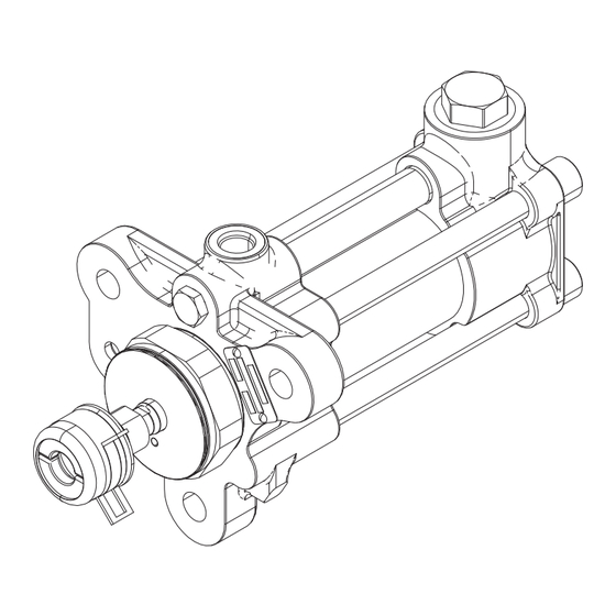
Component Identification Component Identification 40cc pump shown Outlet Housing (C) . 1: Component Identification Key: Displacement Rod (inside main cylinder) Fluid Inlet (bottom of inlet housing) Throat Cartridge Pump Mounting Holes Outlet Housing Pressure Transducer Port Main Cylinder Linear Transducer Mounting Hole Crossover Tube Identification Tag Tie Bolt... -
Page 9: Operation
Operation Operation • Flush at the lowest pressure possible. Check connectors for leaks and tighten as necessary. Pressure Relief Procedure • Flush with a fluid that is compatible with the fluid being dispensed and the equipment wetted parts. Follow the Pressure Relief Procedure whenever Maintenance you see this symbol. -
Page 10: Repair
Repair Repair 4. Remove upper check assembly (AA), including the spring retainer (137), check housing (138), conical spring (139), ball housing retainer (140), ball (141), carbide seat (142), O-ring (143), retainer (144), and O-ring (108). 5. Remove lower check (BB), including the spring retainer (137), check housing (138), conical spring Required Tools (139),ball housing retainer (140), ball (141), carbide... -
Page 11: Inlet Housing Assembly
Repair 3. Remove inlet valve cap (113) from inlet housing 7. Clean all parts in a compatible solvent. Lay the (106), and remove O-ring (108). See F . 5. parts in order for easier reassembly. Inspect each ball and seat for nicks or scratches then replace as required. - Page 12 Repair Models 40cc-160cc, S8 Pumps 1. Apply anti-seize lubricant to the threads of inlet valve cap (113) and install O-ring (108) into the groove. 2. Assemble lower check assembly (DD). Install O-ring (108) into inlet housing (106) followed by the carbide seat (109).
-
Page 13: Pump Disassembly
Repair Pump Disassembly 1. Relieve pressure and flush system. Follow Pressure Relief Procedure and Flushing, page 9. 2. Remove inlet and outlet hoses, drain inlet housing (106), and outlet housing (107). If quick lube system is installed, detach hoses from outlet housing (107). 3. - Page 14 Repair 12. Remove throat cartridge (119). (116), and two piston seals (117). See F . 18 and F . 19. 13. Use o-ring pick and remove o-ring (145) from inside throat cartridge (119), two throat seals (126) out of For 20cc-40cc S8 Pumps the throat cartridge, and O-ring (125) from the shoulder of the throat cartridge.
-
Page 15: Pump Rod Assembly
NOTICE To prevent displacement rod damage, do not clamp directly onto displacement rod surface. Specification sheets and Graco testing indicate that anaerobic sealant requires three days to fully cure. Failure to allow three days for full cure may result in 4. - Page 16 Repair 5. Apply grease to the o-ring (145) and the two throat 9. Install cylinder o-rings (101) on pump cylinder (103) seals (126). Install the o-ring (145) into the upper and crossover tube o-rings (102) on crossover most groove of the throat cartridge (119). slide pump tube (104).
- Page 17 Repair 15. Torque tie bolts (105) in a star pattern (see F . 29) to 10 ft-lbs (13.5 N•m). Then torque again to 50 ft-lbs (67.5 N•m). Torque a final time to 200 ft-lbs (271 N•m) 16. After torquing the four tie bolts (105) ensure the inlet housing (106) is evenly seated onto the pump cylinder (103) and pump crossover tube (104).
-
Page 18: Parts
Mount such that the non-spring end of one seal and the non-spring end of the other seal are joined. Specification sheets and Graco testing indicate that anaerobic sealant requires three days to fully cure. Failure Assemble piston bearing (116), piston seals (117), and piston to allow three days for full cure may result in damage to bearing (116/122) onto piston retainer (114). - Page 19 Assemble piston seals (117) and piston bearing (116) onto pump NOTICE rod bottom (124) before tightening piston retainer (114). Specification sheets and Graco testing indicate that Torque to 70 ft-lbs. (95 N•m). anaerobic sealant requires three days to fully cure. Failure to allow three days for full cure may result in damage to Torque to 30 ft-lbs.
- Page 20 Torque to 200 ft-lbs. (271 N•m). NOTICE See Piston Retainer (114) Torque Specifications table on Specification sheets and Graco testing indicate that page 15 for torque specification. anaerobic sealant requires three days to fully cure. Failure to allow three days for full cure may result in damage to Must be pressed straight into housing.
- Page 21 NOTICE Must be pressed straight into housing. Specification sheets and Graco testing indicate that Apply anti-seize lubricant to threads. anaerobic sealant requires three days to fully cure. Failure to allow three days for full cure may result in damage to Mount such that the non-spring end of one seal and the the equipment from parts coming loose during operation.
- Page 22 Parts S5 and S8 Complete Pump Parts List Pump Size Pump Model No. L005S5 L010S5 L020S8 L040S8 L080S8 L100S8 L0120S8L160S8 . 30 . 33 Ref. Part Description Quantity 106259 PACKING, O-ring, PTFE 108823 111116 PACKING, O-ring, PTFE CYLINDER, pump 15V458 TUBE, crossover, pump 122704 BOLT, tie 15Y165 HOUSING, inlet...
- Page 23 Parts Pump Size Pump Model No. L005S5 L010S5 L020S8 L040S8 L080S8 L100S8 L0120S8L160S8 . 30 . 33 Ref. Part Description Quantity HOUSING, check valve, glass beads SPRING, conical, 1x.85x.281, RETAINER, housing, ball BALL, .500, silicon-nitride, blk 196832 SEAT, sharp, glass beads PACKING, O-ring RETAINER, check valve 103337...
-
Page 24: Various Kits
Parts Various Kits Pump Size 10cc 20cc 40cc 80cc 100cc 120cc 160cc Pump L005S5 L010S5 L020S8 L040S8 L080S8 L100S8 L0120S8 L160S8 Reference Model No. No’s. Figure . 30 . 31 F . 32 . 33 Description Kit No’s. Shaft Adapter 25P039 258966 258967 Not Included Cylinder O-ring Kits... -
Page 25: Seal Kits
Parts Seal Kits 5cc and 10cc Pump Seal Kits NOTE: Some parts shown may appear slightly different in shape and size than actual. 3A8563_kit 26D806 . 34 20cc Pump Seal Kits . 35 3A8563_kit 26B816 40cc and 80cc Pump Seal Kits NOTE: Some parts shown may appear slightly different in shape and size than actual. - Page 26 Parts 100cc and 120cc Pump Seal Kits NOTE: Some parts shown may appear slightly different in shape and size than actual. 3A8563_kit 26B841 . 37 160cc Pump Seal Kit 3A8563_kit 26B847 . 38 Seal Kits, Parts List Pump Size 10cc 20cc 40cc 80cc...
- Page 27 Parts Pump Size 10cc 20cc 40cc 80cc 100cc 120cc 160cc Kit Part No. 26D805 26D806 26B816 26B822 26B829 26B835 26B841 26B847 . 34 . 35 . 36 . 37 . 38 Ref. Description Quantity 125 PACKING, O-ring 126 SEAL, throat, pump, HW 143 PACKING, O-ring 145 PACKING, O-ring 149 PACKING, O-ring...
-
Page 28: Displacement Rod Kits
Parts Displacement Rod Kits 5cc and 10cc Pump Displacement Rod Kit 3A8563_kit 25E472 See Complete Pump Assemblies NOTE: Some parts shown may appear slightly for S5 and S8 page 18 for exploded different in shape and size than actual. view . - Page 29 Parts 100cc and 120cc Pump Displacement Rod Kit See Complete Pump Assemblies for S5 and S8 page 18 for exploded view NOTE: Some parts shown may appear slightly different in shape and size than actual. 3A8563_kit 26B842 . 42 160cc Pump Displacement Rod Kit 3A8563_kit 26B848 See Complete Pump Assemblies for S5 and S8 page 18 for exploded...
-
Page 30: Check Valve Kits, 5Cc, 10Cc S5, 20Cc S8
Parts Pump 10cc 20cc 40cc 80cc 100cc 120cc 160cc Size Kit Part 25N979 25E472 26B817 26B823 26B830 26B836 26B842 26B848 . 39 . 40 . 41 . 42 . 43 Ref. Description Quantity 151 ROD, displacement 152 TOOL, installation LUBRICANT, anti -seize ADHESIVE, anaerobic MANUAL Check Valve Kits, 5cc, 10cc S5, 20cc S8... -
Page 31: Check Valve Kits 40Cc, 80Cc, 100Cc, 120Cc, And 160Cc S8
Parts Check Valve Kits 40cc, 80cc, 100cc, 120cc, and 160cc S8 From kit to kit, quantities of a given part may vary from that pictured. Refer to quantities shown in the table. 3A8563_kit chkvlv 20cc . 45 Check Valve Kits, 40cc, 80cc, 100cc, 120cc, and 160cc S8 Parts List Pump Type Kit Part No. -
Page 32: O-Ring Inlet Kit, All Pump Sizes
Parts O-Ring Inlet Kit, All Pump Sizes 3A8563_kit O-ring 8 . 46 3A8563_kit O-ring 8 . 47 O-Ring Inlet Kit, All Pump Sizes, Parts List Pump Size 5cc, 10cc, 20cc, 40cc, 80cc, 100cc, 120cc, 160cc Kit Part No. 258775 258776 . - Page 33 Parts 3A8563H...
-
Page 34: Dimensions
Dimensions Dimensions All pump sizes have the same dimensions. (Length) (Inlet) (Outlet) in. (mm) in. npt (f) SAE (f) 13.36 (339.34) 3/4-14 3/4-16 Outlet Housing Mounting Hole Layout All pumps have the same outlet housing mounting hole layout. 5.9 in (150 mm) 3A8563H... -
Page 35: Technical Specifications
Technical Specifications Technical Specifications Z-Series Chemical Pumps High Wear Metric Maximum working pressure 3500 psi 24 MPa, 241 bar Maximum operating temperature 180°F 82°C Maximum cycle rate 65 cycles per minute Minimum feed pressure at inlet 50 psi 0.35 MPa, 3.5 bar Materials of Construction SST, tungsten carbide, PEEK, PTFE, UHMWPE, silicon Wetted materials on all models... -
Page 36: Graco Standard Warranty
With the exception of any special, extended, or limited warranty published by Graco, Graco will, for a period of twelve months from the date of sale, repair or replace any part of the equipment determined by Graco to be defective.
Need help?
Do you have a question about the Z-Pump Elite S5 Series and is the answer not in the manual?
Questions and answers