Table of Contents
Advertisement
Quick Links
Instructions-Parts
Z-Pump S1, S3, and
S4 Series
For pumping plural component materials. For professional use only.
Not for use in explosive atmospheres.
3500 psi (24 MPa, 241 bar) Maximum Working Pressure
See page 3 for model information, including maximum working pressure and approvals.
Important Safety Instructions
Read all warnings and instructions in this
manual before using the equipment.
Save these instructions.
3A0019ZAC
EN
r_257891_3a0019_1h
Advertisement
Table of Contents

Related Manuals for Graco Z-Pump S1 Series


Summary of Contents for Graco Z-Pump S1 Series
- Page 1 Instructions-Parts Z-Pump S1, S3, and S4 Series 3A0019ZAC For pumping plural component materials. For professional use only. Not for use in explosive atmospheres. 3500 psi (24 MPa, 241 bar) Maximum Working Pressure See page 3 for model information, including maximum working pressure and approvals. Important Safety Instructions Read all warnings and instructions in this manual before using the equipment.
-
Page 2: Table Of Contents
Grease Cup Maintenance ....10 Graco Information ......50... -
Page 3: Models
Models Models Model Pump Size System Used On Model Pump Size System Used On L070S4 70cc *L005S1 L075S4 75cc L010S1 10cc L080S4 80cc L015S1 15cc L086S4 86cc L020S1 20cc L090S4 90cc L025S1 25cc L100S4 100cc L030S1 30cc L105S4 105cc L035S1 35cc L120S4 120cc... -
Page 4: Warnings
Warnings Warnings The following warnings are for the setup, use, grounding, maintenance, and repair of this equipment. The exclamation point symbol alerts you to a general warning and the hazard symbol refers to procedure-specific risk. Refer back to these warnings. Additional, product-specific warnings may be found throughout the body of this manual where applicable. - Page 5 Warnings WARNING EQUIPMENT MISUSE HAZARD Misuse can cause death or serious injury. • Do not operate the unit when fatigued or under the influence of drugs or alcohol. • Do not exceed the maximum working pressure or temperature rating of the lowest rated system component.
- Page 6 Warnings WARNING TOXIC FLUID OR FUMES HAZARD Toxic fluids or fumes can cause serious injury or death if splashed in the eyes or on skin, inhaled or swallowed. • Read Safety Data Sheets (SDSs) for handling instructions and to know the specific hazards of the fluids you are using, including the effects of long-term exposure.
-
Page 7: Important Isocyanate (Iso) Information
Important Isocyanate (ISO) Information Important Isocyanate (ISO) Information Isocyanate Conditions Keep Components A and B Separate Spraying or dispensing fluids that contain isocyanates creates potentially harmful mists, vapors, and atomized particulates. Cross-contamination can result in cured material in fluid lines which could cause serious injury or damage equipment. -
Page 8: Keep Components A And B Separate
Never store ISO in an open container. • Keep the ISO lube pump reservoir (if installed) filled ™ with Graco Throat Seal Liquid (TSL ), Part 206995. The lubricant creates a barrier between the ISO and the atmosphere. •... -
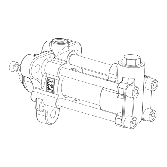
Page 9: Component Identification
Component Identification Component Identification 40cc pump shown Outlet Housing (C) . 1: Component Identification Key: Displacement Rod (inside main cylinder) Pressure Transducer Port Throat Cartridge/Retainer Linear Transducer Mounting Hole Outlet Housing Identification Tag Main Cylinder Rod Adapter (not on all models) Crossover Tube Pump Coupler Coupler Cover... -
Page 10: Operation
Operation Operation • Flush with a fluid that is compatible with the fluid being dispensed and the equipment wetted parts Pressure Relief Procedure Maintenance Follow the Pressure Relief Procedure whenever NOTE: If the quick lube system is installed on the you see this symbol. -
Page 11: Repair
Repair Repair 4. Remove upper ball cage housing (112), ball check spring (111), SST ball (110), O-ring (108) and carbide seat (109). 5. Press lower SST ball (110) off carbide seat (109) from fluid inlet and drain the inlet housing (106). 6. - Page 12 Repair 2. Remove inlet hose and drain inlet housing (106). 6. Clean all parts in a compatible solvent. Lay them in See F . 5. order for easier reassembly. Inspect each ball and seat for nicks or scratches; replace as required. 3.
-
Page 13: Inlet Housing Assembly
Repair Inlet Housing Assembly Model S4 Pumps 1. When installing the inlet housing components: Model S1 Pumps a. Apply anti-seize lubricant to the ball cage 1. Apply anti-seize lubricant to the threads of inlet housing (138) and retainers (137 and 144). valve cap (113) and install O-ring (108) into the groove. -
Page 14: Pump Disassembly
Repair Pump Disassembly 1. Relieve pressure and flush system. Follow Pressure Relief Procedure and Flushing, page 2. Remove inlet hose and drain inlet housing (106). 3. Using a bench vice, Horizontally clamp the pump on outlet housing (107). Use a 1/2 in. hex bit socket . - Page 15 Repair 12. Remove Cartridge (118). For 60cc-160cc S1, S3, and S4 Pumps 13. Use O-ring pick and remove O-ring (145)and two throat seals (126) out of the throat cartridge (118). see F . 13. 14. Remove throat retainer (119) and throat cartridge .
-
Page 16: Pump Rod Assembly
A NOTICE (isocyanate) and component B (resin) parts. Specification sheets and Graco testing indicate that anaerobic sealant requires three days to fully cure. Failure to allow three days for full cure may result in NOTICE parts coming loose during operation. - Page 17 Repair Piston Retainer (114) Torque into the throat cartridge until it contacts the first throat seal. See F . 19. Specifications: Pump Size Torque 3.2 ft-lbs (4.3 N•m) 10cc 5.5 ft-lbs (7.4 N•m) 101/125 15cc 5.5 ft-lbs (7.4 N•m) 20cc 30 ft-lbs (40.8 N•m) 25cc 30 ft-lbs (40.8 N•m)
- Page 18 Repair . 21 13. Install pump cylinder (103) and pump crossover . 23 tube (104) in outlet housing (107) with a rubber mallet. See F . 22 page 18. 15. Install displacement rod (151) in pump cylinder (103) and into throat cartridge (118). Gently tap displacement rod with a rubber mallet until the hex surface of the piston retainer (114) is flush or below the surface of the pump cylinder.
- Page 19 Repair 18. Torque tie bolts (105) in a star pattern to 10 ft-lbs 21. For 10cc-50cc pumps only: Clean rod adapter (121) (13.5 N•m). Then torque again to 50 ft-lbs (67.5 threads with a wire brush and apply removable N•m). Torque a final time to 200 ft-lbs (271 N•m) strength thread locker to displacement rod (115) 19.
-
Page 20: Parts
NOTICE Must be pressed straight into housing. Specification sheets and Graco testing indicate that Apply anti-seize lubricant to threads. anaerobic sealant requires three days to fully cure. Failure to allow three days for full cure may result in parts coming Mount seals such that the non-spring end of one seal and the non-spring end of the other seal is joined. - Page 21 NOTICE Must be pressed straight into housing. Specification sheets and Graco testing indicate that Apply anti-seize lubricant to threads. anaerobic sealant requires three days to fully cure. Failure to allow three days for full cure may result in parts coming Mount seals such that the non-spring end of one seal and the non-spring end of the other seal is joined.
- Page 22 NOTICE Apply anti-seize lubricant to threads. Specification sheets and Graco testing indicate that Mount seals such that the non-spring end of one seal and the anaerobic sealant requires three days to fully cure. Failure non-spring end of the other seal is joined.
- Page 23 Parts S1 and S3 Complete Pump Parts List S1 Pump Size 5cc, 10cc, 15cc, 20cc, 25cc, 30cc, 35cc, 40cc, 50cc, 60cc, 65cc, and 70cc Series Pump Size (cc) Model No. Figure . 26 . 27 . 28 Ref. Part Description Quantity 108822 PACKING, O-Ring, PTFE...
- Page 24 Parts Series Pump Size (cc) Model No. Figure . 26 . 27 . 28 Ref. Part Description Quantity PLATE, ID SCREW, drive 15G923 COUPLER 198031 197340 COVER, coupler 103337 111710 103338 103610 115719 108195 106553 555684 C38312 103413 PACKING, O-ring 115929 188555 110073...
- Page 25 Parts S1 Pump Size 75cc, 80cc, 86cc, 90cc, 100cc, 105cc, 120cc, 140cc, 150cc, and 160cc S3 Pump Size 10cc and 20cc Series Pump Size Model No. Figure . 43 . 27 F . 28 Ref. Part Description Quantity 108822 O-Ring, CYL 106259 111116 O-Ring, tube CYLINDER...
- Page 26 Parts Series Pump Size Model No. Figure . 43 . 27 F . 28 Ref. Part Description Quantity SCREW, drive 15G923 COUPLER 198031 197340 COVER, coupler 103337 111710 103338 103610 115719 108195 106553 555684 C38312 103413 PACKING, O-ring 115929 188555 110073 559013 103559...
- Page 27 Parts S4 Pump Parts Lists S4 Pump Size 5cc, 10cc, 15cc, 20cc, 25cc, 30cc, 35cc, 40cc, 50cc, 60cc, 65cc, and 70cc Series Pump Size (cc) Pump Model No. Figure . 27 . 28 . 43 Ref. Part Description Quantity 108822 PACKING, O-Ring 106259 111116 PACKING, O-Ring, PTFE...
- Page 28 Parts Series Pump Size (cc) Pump Model No. Figure . 27 . 28 . 43 Ref. Part Description Quantity 197340 COVER, coupler 17E794 CAP, inlet, valve, SQ,HD RETAINER, spring HOUSING, ball, cage SPRING, ballcheck RETAINER, HSG, ball BALL, 0.500, silicon, NIT 196832 SEAT, ball 119740 PACKING, O-RING RETAINER, check, VA...
- Page 29 Parts S4 Pump Size 75cc, 80cc, 86cc, 90cc, 100cc, 105cc, 120cc, 140cc, 150cc, and 160cc (cc) Series Pump Size Pump Model No. Figure . 28 Ref. Part Description Quantity 108822 PACKING, O-ring, PTFE 106259 111116 PACKING, O-Ring, PTFE CYLINDER 15V458 TUBE, cross 122704 SCREW, CSH 15Y165 HOUSING, inlet 15X946 HOUSING, outlet...
- Page 30 Parts Series Pump Size Pump Model No. Figure . 28 Ref. Part Description Quantity 17E794 CAP, inlet, valve, SQ,HD RETAINER, spring HOUSING, ball, cage SPRING, ballcheck RETAINER, HSG, ball BALL, 0.500, silicon, NIT 196832 SEAT, ball 119740 O-RING, check, VA RETAINER, check, VA 103337 111710...
-
Page 31: Various Kits
Parts Various Kits Pump Size (cc) 10cc 15cc 20cc 25cc 30cc 35cc 40cc Pump Model Figure . 26 . 27 Reference Description Kit No. No’s. Shaft Adapter Cylinder O-ring Kt 259774 101, 102 101, 102, Cylinder Kit 103, 150 Crossover Tube 24E557 102, 104 Piston Retainer Kit... - Page 32 Parts Pump Size (cc) 45cc 50cc 60cc 65cc 70cc 75cc 80cc 86cc 90cc Pump Model No. . 28 . 29 Reference Kit No. Shaft Adapter 258786 Not Included Cylinder O-ring kit 258774 258773 101, 102 101, 102, Cylinder Kit 24R311 258801 258807 24H998 25C252 24N821 258813 24H999 24T165 103, 150 Crossover Tube 24E557...
-
Page 33: Seal Kits
Parts Seal Kits 5cc, 10cc, and 15cc Pump Seal Kits (S1, S3, S4) S4 Only (S1, S3) S4 Only NOTE: Some parts shown may appear slightly different in shape and size than actual. . 29 3A0019_kitseal_1 20cc, 25cc, 30cc, 35cc, 40cc, 45cc, and 50cc Pump Seal Kits S4 Only (S1, S3, S4) (S1, S3) - Page 34 Parts 120cc, 140cc, and 150cc Pump Seal Kits (S1, S3, S4) S4 Only (S1, S3) S4 Only NOTE: Some parts shown may appear slightly different in shape and size than actual. 3A0019_kitseal_4 . 32 160cc Pump Seal Kit (S1, S3, S4) S4 Only (S1, S3) S4 Only...
- Page 35 Parts Pump Size (cc) 10cc 15cc 20cc 25cc 30cc 35cc 40cc Pump Model No. Seal Kit Part No. . 29 . 30 Ref. Description Quantity 108 PACKING O-ring 116 SEAL, piston 117 BEARING, piston 120 PACKING, O-ring 121 ADAPTER, rod 125 PACKING, O-ring 126 SEAL, throat 145 PACKING, O-ring...
- Page 36 Parts Pump Size (cc) 45cc 50cc 60cc 65cc 70cc 75cc 80cc 86cc 90cc Pump Model No. Seal Kit Part No. . 30 . 31 Ref. Description Quantity 101 PACKING, O-ring, PTFE 102 PACKING, O-ring, seat 108 PACKING O-ring 116 SEAL, piston 117 BEARING, piston 120 PACKING, O-ring 121 ADAPTER, rod...
- Page 37 Parts Pump Size (cc) 100cc 105cc 120cc 140cc 150cc 160cc Pump Model No. Seal Kit Part No. . 31 Ref. Description Quantity 101 PACKING, O-ring, PTFE 102 PACKING, O-ring, seat 108 PACKING O-ring 116 SEAL, piston 117 BEARING, piston 120 PACKING, O-ring 121 ADAPTER, rod 125 PACKING, O-ring 126 SEAL, throat...
-
Page 38: Displacement Rod Kits
Parts Displacement Rod Kits 5cc, 10cc, and 15cc Pump Displacement Rod Kits 3A0019_kitrod_1 See Complete Pump Assemblies for S1, S3, and S4 page 20 for exploded view of 151 NOTE: Some parts shown may appear slightly different in shape and size than actual. . - Page 39 Parts 100cc, 120cc, 140cc, and 150cc Pump Displacement Rod Kits See Complete Pump Assemblies for S1, S3, and S4 page 20 for exploded view of 151 NOTE: Some parts shown may appear slightly different in shape and size than actual. 3A0019_kitrod_4 .
- Page 40 Parts Displacement Rod Kits Parts List Note: See S1 and S3 Complete Pump Parts List page 23, and S4 Pump Parts Lists page 27 for part numbers Pump Size (cc) 10cc 15cc 20cc 25cc 30cc 35cc 40cc Pump Model No. Displacement Rod Kit Part No.
- Page 41 Parts Pump Size (cc) 45cc 50cc 60cc 65cc 70cc 75cc 80cc 86cc 90cc Pump Model No. Displacement Rod Kit Part No. . 30 . 31 Ref. Description Quantity 101 PACKING, O-ring, PTFE 102 PACKING, O-ring, seat 120 PACKING, O-ring 121 ADAPTER, rod 125 PACKING, O-ring 126 SEAL, throat 145 PACKING, O-ring...
- Page 42 Parts Pump Size (cc) 100cc 105cc 120cc 140cc 150cc 160cc Pump Model No. Displacement Rod Kit Part No. . 31 Ref. Description Quantity 101 PACKING, O-ring, PTFE 102 PACKING, O-ring, seat 120 PACKING, O-ring 121 ADAPTER, rod 125 PACKING, O-ring 126 SEAL, throat 145 PACKING, O-ring TOOL, displacement...
-
Page 43: Check Valve Kits For S1 And S3 Pumps
Parts Check Valve Kits for S1 and S3 Pumps . 39 3A8563_kit chkvlv 20cc Check Valve Kits for S1 and S3 Pumps, Parts List Note: For parts numbers see S1 and S3 Complete Pump Parts List page 23 Pump Type S1 and S3 Kit Part No. -
Page 44: Check Valve Kits For S4 Pumps
Parts Check Valve Kits for S4 Pumps . 40 3A0019_kit chkvlv 20cc Check Valve Kits for S4 Pumps, Parts List Note: For parts numbers see S4 Pump Parts Lists page 27 Pump Type Kit Part No. 25B123 25B124 26D040 Sharp Kit Type Full Partial... -
Page 45: O-Ring Inlet Kit, All Pump Sizes
Parts O-Ring Inlet Kit, All Pump Sizes 3A8563_kit O-ring 8 3A8563_kit O-ring 8 . 41 . 42 O-Ring Inlet Kit, All Pump Sizes, Parts List 5cc, 10cc, 20cc, 40cc, 80cc, 100cc, 120cc, Pump Size 160cc Kit Part No. 258775 258776 . -
Page 46: Z-Pump Grease Cup Conversion Kits
Parts Z-Pump Grease Cup Conversion after removing them from the outlet housing (107), see F . 43. Kits The kits listed below are for converting older model Z-Pumps without grease cups. The older model Z-Pumps may have a wet cup configuration which has been obsoleted. - Page 47 Parts 3A0019ZAC...
-
Page 48: Dimensions
Dimensions Dimensions All pump sizes have the same dimensions. r_257891_3a0019_22h (Length) (Inlet) (Outlet) in. (mm) in. npt (f) SAE (f) 13.36 (339.34) 3/4-14 3/4-16 Outlet Housing Mounting Hole Layout All pumps have the same outlet housing mounting hole layout. 5.9 in (150 mm) r_257891_3a0019_23h 3A0019ZAC... -
Page 49: Technical Specifications
Technical Specifications Technical Specifications Maximum working pressure ..... . . 3500 psi (24MPa, 241 bar) Maximum operating temperature ....180° F (82° C) Maximum cycle rate . -
Page 50: Graco Standard Warranty
With the exception of any special, extended, or limited warranty published by Graco, Graco will, for a period of twelve months from the date of sale, repair or replace any part of the equipment determined by Graco to be defective.
Need help?
Do you have a question about the Z-Pump S1 Series and is the answer not in the manual?
Questions and answers